|

|
Supply Chain Management Sample Application Architecture
Document Status:
Final Specification
Version:
1.01
Date:
December 9, 2003
Editors:
Martin Chapman, Oracle
Marc Goodner, SAP
Brad Lund, Intel
Barbara McKee, IBM
Rimas Rekasius, IBM |
Notice
The material contained herein is not a
license, either expressly or impliedly, to any intellectual property owned
or controlled by any of the authors or developers of this material or WS-I.
The material contained herein is provided on an "AS IS" basis and to the
maximum extent permitted by applicable law, this material is provided AS IS
AND WITH ALL FAULTS, and the authors and developers of this material and
WS-I hereby disclaim all other warranties and conditions, either express,
implied or statutory, including, but not limited to, any (if any) implied
warranties, duties or conditions of merchantability, of fitness for a
particular purpose, of accuracy or completeness of responses, of results, of
workmanlike effort, of lack of viruses, and of lack of negligence. ALSO,
THERE IS NO WARRANTY OR CONDITION OF TITLE, QUIET ENJOYMENT, QUIET
POSSESSION, CORRESPONDENCE TO DESCRIPTION OR NON-INFRINGEMENT WITH REGARD TO
THIS MATERIAL.
IN NO EVENT WILL ANY AUTHOR OR DEVELOPER OF
THIS MATERIAL OR WS-I BE LIABLE TO ANY OTHER PARTY FOR THE COST OF PROCURING
SUBSTITUTE GOODS OR SERVICES, LOST PROFITS, LOSS OF USE, LOSS OF DATA, OR
ANY INCIDENTAL, CONSEQUENTIAL, DIRECT, INDIRECT, OR SPECIAL DAMAGES WHETHER
UNDER CONTRACT, TORT, WARRANTY, OR OTHERWISE, ARISING IN ANY WAY OUT OF THIS
OR ANY OTHER AGREEMENT RELATING TO THIS MATERIAL, WHETHER OR NOT SUCH PARTY
HAD ADVANCE NOTICE OF THE POSSIBILITY OF SUCH DAMAGES.
Status of this
Document
This is a
final specification. Readers should refer to the
WS-I.org web site for errata and updates.
TOC \o "3-3" \h \z \t
"Heading 1,1,Heading 2,2"
1..
Introduction.
PAGEREF _Toc45557380 \h 4
2..
Document References.
PAGEREF _Toc45557381 \h 5
3..
Retailer System Architecture.
PAGEREF _Toc45557382 \h 5
3.1....
Retailer System Glossary.
PAGEREF _Toc45557383 \h 5
3.2....
Retailer System Overview.
PAGEREF _Toc45557384 \h 6
3.3....
Deployment Diagram..
PAGEREF _Toc45557385 \h 6
3.4....
Retailer System Web services.
PAGEREF _Toc45557386 \h 7
3.4.1
Retailer Service.
PAGEREF _Toc45557387 \h 8
3.4.2
Warehouse Service.
PAGEREF _Toc45557388 \h 9
3.4.3
Warehouse Callback Service.
PAGEREF _Toc45557389 \h 10
3.4.4
WSDL
PAGEREF _Toc45557390 \h 11
3.5....
Class Diagram..
PAGEREF _Toc45557391 \h 12
3.6....
Sequence Diagrams.
PAGEREF _Toc45557392 \h 13
3.6.1
UC1: Purchase Goods.
PAGEREF _Toc45557393 \h 13
3.6.2
UC2: Source Goods.
PAGEREF _Toc45557394 \h 13
3.6.3
UC3: Replenish Stock.
PAGEREF _Toc45557395 \h 14
4..
Manufacturing System Architecture.
PAGEREF _Toc45557396 \h 15
4.1....
Manufacturing System Glossary.
PAGEREF _Toc45557397 \h 15
4.2....
Manufacturing System Overview.
PAGEREF _Toc45557398 \h 15
4.3....
Deployment Diagram..
PAGEREF _Toc45557399 \h 15
4.4....
Manufacturing System Web services.
PAGEREF _Toc45557400 \h 16
4.4.1
Manufacturer Service.
PAGEREF _Toc45557401 \h 17
4.4.2
WSDL
PAGEREF _Toc45557402 \h 18
4.5....
Class Diagram..
PAGEREF _Toc45557403 \h 18
4.6....
Sequence Diagrams.
PAGEREF _Toc45557404 \h 19
4.6.1
UC4: Supply Finished Goods & UC5: Manufacture Finished Goods.
PAGEREF _Toc45557405 \h 20
5..
Demo System Architecture.
PAGEREF _Toc45557406 \h 20
5.1....
Demo System Glossary.
PAGEREF _Toc45557407 \h 21
5.2....
Sample Application Flow.
PAGEREF _Toc45557408 \h 21
5.3....
Deployment Diagram..
PAGEREF _Toc45557409 \h 22
5.4....
Demo System Web services.
PAGEREF _Toc45557410 \h 23
5.4.1
Configurator
PAGEREF _Toc45557411 \h 24
5.4.2
Configurator WSDL.
PAGEREF _Toc45557412 \h 25
5.4.3
Logging Facility.
PAGEREF _Toc45557413 \h 25
5.4.4
Logging Facility WSDL.
PAGEREF _Toc45557414 \h 27
5.5....
Class Diagram..
PAGEREF _Toc45557415 \h 27
5.6....
Sequence Diagrams.
PAGEREF _Toc45557416 \h 28
5.6.1
UC6: Configure & Run Demo.
PAGEREF _Toc45557417 \h 29
5.6.2
UC7: Log Events.
PAGEREF _Toc45557418 \h 30
5.6.3
UC8: View Events.
PAGEREF _Toc45557419 \h 31
6..
Design Aspects of the Basic Sample Application.
PAGEREF _Toc45557420 \h 31
6.1....
Basic Sample Application User Interface Fundamentals.
PAGEREF _Toc45557421 \h 31
6.2....
Basic Sample Application Web Service Descriptions.
PAGEREF _Toc45557422 \h 32
6.3....
Basic Callback Usage Scenario Design and Implementation.
PAGEREF _Toc45557423 \h 33
6.4....
UDDI Advertisement of the Basic Sample Application.
PAGEREF _Toc45557424 \h 33
6.4.1
Advertisement of tModels.
PAGEREF _Toc45557425 \h 34
6.4.2
Advertisement of Web Service Implementations.
PAGEREF _Toc45557426 \h 35
6.4.3
Participation in the WS-I Interoperability Showcase.
PAGEREF _Toc45557427 \h 36
6.4.4
businessService Categorizations To Differentiate Roles.
PAGEREF _Toc45557428 \h 37
6.5....
Event Logging in the Basic Sample Application.
PAGEREF _Toc45557429 \h 37
6.6....
State Data Used by the Basic Sample Application.
PAGEREF _Toc45557430 \h 39
This document details the technical design and
implementation of the Basic Profile 1.0 Sample Application. The sample
application described herein was modeled after the “simple” supply chain
management (SCM) application outlined in the SCM Use Cases V1.0 document; it is
not intended to exhibit all of the characteristics of a real world SCM design
and implementation. Rather, it serves to document and demonstrate how WS-I Basic
Profile 1.0 conformant web services might be designed, implemented and
deployed.
One of the goals of the Sample Application is to explore
as many of the features found in the Basic Profile as possible. To this end, the
sample application employs a variety of schema naming conventions, SOAP message
formats, SOAP message styles, and WSDL design practices that are all Basic
Profile conformant. In many places coverage of Basic Profile features has been
traded for best practice.
To fully understand the contents of this document it is
highly recommended that the SCM Use Cases v 1.0 as well as the Usage
Scenarios v 1.0 documents be consulted in conjunction with this document. A
quick overview of the various stages of interactions for the Sample Application
can be found in section 5.2, Figure 9.
In order to inject some realism into the sample
application, a single top down design was not attempted. Rather each main system
(Retailer, Manufacture, Demo) has been designed and architected separately and
brought together via web services. This should reflect the real world of
connecting autonomous organizations together without the luxury of a global
architecture and design.
The document is divided into four main sections and has
an intended audience which includes Architects, Designers and Implementers of
WS-I compliant web services. Each section of this document starts with a
glossary of terms used to help clarify specific areas of discussion.
Section 3, “Retailer System Architecture”: This section
provides an in-depth look at the various web services and associated methods
required for a consumer to order product and simultaneously receive a response
indicating which items were shipped. Additionally, this section describes a web
service that is invoked by the retailer’s warehouse which checks each line item
in the order for product availability.
Included in this section are several architectural
diagrams that provide different views of the application mechanics, including
interfaces, roles and responsibilities, business rules to help facilitate WSDL
design, processes as well as the information collected and maintained. Also,
the reader will discover which usage scenarios were implemented as well as the
recommended message style.
Section 4, “Manufacturing System Architecture”: Here we
look at the various web services and associated methods required to supply
finished goods to the warehouses. Like Section 3, this section contains
detailed architectural mechanics, usage scenario and message style selection as
they relate to the manufacturing architecture.
Section 5, “Demo System”: This section examines how
various use cases were implemented in the development of the demo application
that will be showcased on the WS-I web site. Section 5.2 provides the reader
with a step-by-step roadmap of the processes involved to interact with the
demo. Like previous sections, this section contains detailed architectural
mechanics, usage scenario and message style selection as they relate to specific
pieces of the demo application.
Section 6. “Design Aspects of the Basic Sample
Application”: This section describes the technical design aspects of the Basic
Sample Application. The technical descriptions of the Web services and their
associated schemas are included here, as are the fundamentals of the showcase
User Interface, logging of events, fixed sample data, and the advertisement of
sample Web services in UDDI. The reader will find several examples of XML code
to assist them in the UDDI registration of their web services.
|
Document |
Description |
|
Usage Scenarios |
This document describes Usage Scenarios, as defined by
the Scenarios and Design Sub-team of the Basic Sample Applications
Workgroup for the WS-I. |
|
SCM Use Cases |
This document contains the use cases on which this
Architecture and Domain Model has been based. |
This section pertains to the technical design and
implementation of the Basic Profile Sample Application. In particular it defines
the Retailer part of the system defined in the SCM use case document.
The domain model and architecture described in this
section relates to the retailer system and its related use cases as defined in
the SCM Use Cases v 1 document, and as such should be read in conjunction
with that document.
The various types of diagrams (class, sequence,
deployment, etc.) included in this section each provide a different view of the
application, including its interfaces, roles and responsibilities, business
rules, processes as well as the information collected and maintained.
In general this model is implementation independent
except where technical constraints are given as part of the requirements.
|
Term |
Description |
|
Catalog |
A listing of catalog entries |
|
Catalog Entry |
The details about a product (name, description,
category, price, etc) |
|
Consumer |
A party that wishes to purchase product from a Retailer |
|
Inventory Item |
The details of a product as it relates to a warehouse
(product code, warehouse location, number in stock, minimum stock level,
maximum stock level) |
|
Line Item |
An entry in an order relating to a single product
(product code, required quantity) |
|
Manufacturer |
A party that supplies finished goods to a Retailer’s
warehouses. |
|
Order (or Purchase Order/PO) |
A request from a Consumer asking to purchase
products. An order consists of one or more line items |
|
Product |
A tangible entity that can be sold – finished goods |
|
Shipping Notice (SN) |
A notice sent to a consumer in response to a purchase
order stating that the line items have been shipped. |
|
Retailer |
A party that offers products for sale |
|
Warehouse |
An entity that stores products and maintains an
Inventory level for each stocked product |
The Retailer will present a Web service for some third
party system to access its services. In the Sample Application this will be the
Demo System. The Retailer web service provides a façade onto the Retailer
System, providing operations to access the catalog of products and to place
orders. Within the Retailer System there are three instances of the warehouse
web services, one for each of warehouse A, B and C defined in the Use Case
document. These warehouses will in turn call out to the three Manufacturing
systems, whose architecture is defined in Section 4.
To facilitate this interaction the warehouse has to provide a callback interface
– these and the retailer web service are the only external entry points into the
Retailer system. For the purpose of the Sample Application the Retailer System
relies on the Logging service provided by the Demo System.
Figure 1 shows a conceptual view of an implementation of
a Retailer System.
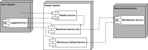
Figure SEQ Figure \* ARABIC 1: Retailer System Deployment
Diagram
The operations, message types and other relevant
information for each Web service are outlined in the sections below. These
sections specify key details to be defined in the associated WSDL files. The
exact structure of these files is to be resolved as part of the implementation
of this sample application.
The Retailer System will contain the following web
services:
·
Retailer Service
·
Warehouse Service
·
Warehouse Callback Service.
In addition, the Retailer System depends on two other
services external to itself and defined elsewhere:
Logging Service - defined in the Demo System section.
Manufacturer Service – defined in the Manufacturing
System section.
Profiles
The web services will be based on the WS-I Basic Profile
V1.0.
Usage Scenarios
The web services in the retailer system will rely on the
following usage scenarios (refer to Usage Scenarios document):
·
Synchronous Request/Response
·
Basic Callback
·
One-way
Operations/Message Types
The following operations/message types should be
supported, and shall follow the synchronous request/reply scenario:
|
Operation |
Msg. Type |
Message |
Parameters |
Type |
|
submitOrder |
Input |
submitOrderRequest |
PartsOrder |
PartsOrderType |
|
|
|
|
Customer Details |
CustomerDetailsType |
|
|
|
|
ConfigurationHeader |
Configuration |
|
|
Output |
submitOrderResponse |
Response |
PartsOrderResponseType |
|
|
Fault |
BadOrder |
|
Client |
|
|
Fault |
InvalidProductCode |
|
Client |
|
|
Fault |
ConfigurationFault |
|
Client |
|
Operation |
Msg. Type |
Message |
Parameters |
Type |
|
getCatalog |
Input |
getCatalogRequest |
|
|
|
|
Output |
getCatalogResponse |
return |
CatalogType |
3.4.1.1
submitOrder
Description
Refer to UC (Use Case)1 and UC2.
The consumer submits an order and receives a response indicating which goods
will be shipped. To determine which goods can be shipped Warehouse A, B, and C
are asked in turn (see warehouse service).
The input of the
submitOrder
operation is a PartsOrder
of type PartsOrderType.
This is a sequence of items consisting of “productNumber”, “quantity”, and
“price”. The output of the
submitOrder operation is a
Response of type
PartsOrderResponseType. This is a
sequence of items consisting of “productNumber”, “quantity”, “price”, and
“comment”. Each “productNumber” in the request will have a corresponding item
in the response. In the response, the “quantity” will either be the same as the
“quantity” in the request, or zero if no Warehouse is able to fulfill the
order. Also, the “price” in the response is actually the sub-total for that
particular item, which is calculated as the “quantity” in the response times the
product price as obtained from the product catalog (i.e. not the
“price” in the request).
A
BadOrder
fault is returned if the order is malformed and cannot be interpreted, or
contains no line items.
An order is rejected, with an
InvalidProductCode
fault, if it contains a line item with an invalid (i.e. unknown) product code.
A
ConfigurationFault fault is returned if
there is a problem in the configuration header.
Scenario
The scenario used will be
Synchronous Request/Response using SOAP over HTTP.
Message Style
The rpc/literal message style
will be used.
3.4.1.2
getCatalog
Description
Refer to UC1. A call to this
operation results in the Retailer sending over the list of products that it
sells, this list would need to be rendered in order to present to a user. There
are no input parameters as there is no choice of catalogs or parts of a catalog.
Scenario
The scenario used will be
Synchronous Request/Response using SOAP over HTTP.
Message Style
The the rpc/literal message
style will be used.
Operations/Message Types
The following operations/message types should be
supported, and all shall follow the synchronous request/reply scenario:
|
Operation |
Msg. Type |
Message |
Parameters |
Type |
|
ShipGoods |
Input |
ShipGoodsRequest |
ItemList |
ItemList |
|
|
|
|
Customer |
CustomerReferenceType |
|
|
|
|
ConfigurationHeader |
Configuration |
|
|
Output |
ShipGoodsResponse |
Response |
ItemShippingStatusList |
|
|
Fault |
ConfigurationFault |
|
Client |
3.4.2.1
ShipGoods
Description
Refer to UC 1 and UC2. A call to
this service results in the warehouse checking each line item in the order. If
for each line item the required quantity is in stock, the warehouse will ship
that line item (and hence reduce the stock level). It will record which ones it
has shipped and which ones it does not have enough stock for and hence cannot
ship; the response will contain this list.
A
ConfigurationFault fault is returned if
there is a problem in the configuration header.
The reduction of the stock level
below the minimum level will trigger the warehouse to call on the Supply service
of the relevant manufacturer (defined in the Manufacturing System Domain Model
and Architecture section).
Scenario
The scenario used will be
Synchronous Request/Response using SOAP over HTTP.
Message Style
The rpc/literal message style
will be used.
Operations/Message Types
The following operations/message types should be
supported:
|
Operation |
Msg. Type |
Message |
Parameters |
Type |
|
SubmitSN |
Input |
SNSubmit |
shippingNotice |
doc |
|
|
|
|
ConfigurationHeader |
Configuration |
|
|
|
|
CallbackHeader |
CallbackHeader |
|
|
Output |
ackSN |
Response |
boolean |
|
|
Fault |
ConfigurationFault |
|
Client |
|
|
Fault |
CallbackFault |
|
Server |
|
Operation |
Msg. Type |
Message |
Parameters |
Type |
|
ErrorPO |
Input |
ProcessPOFault |
ProcessPOFault |
SubmitPOFault |
|
|
Output |
AckPO |
Repsonse |
boolean |
|
|
Fault |
ConfigurationFault |
|
Client |
|
|
Fault |
CallbackFault |
|
Server |
3.4.3.1
SubmitSN
Description
Refer to UC3 and UC4. A call to
this service indicates that the manufacturer has finished processing an order.
If the manufacturer’s processing
has been successful, the manufacturer will submit the shipping notice using the
SubmitSN
operation. If the shipping notice can be correlated to an order placed with a
manufacturer, a positive acknowledgement is sent in the reply; otherwise a
callbackfault is
returned.
In this version of the sample
application, all responses will cause the Manufacturer to consider the order
request complete i.e. no further processing of the order will take place.
Scenario
The scenario used will be the
reply/callback portion of the Basic Callback Scenario using SOAP over HTTP.
Message Style
The doc/literal message style
will be used.
3.4.3.2 ErrorPO
Description
Refer to Use cases 3 and 4. A
call to this service indicates that the manufacturer has finished processing an
order but there had been an error in doing so.
If the Manufacturer’s processing
of the order has not been successful, the Manufacturer will provide a reason
using the ErrorPO
operation.
For any PO, a Manufacturer may
only invoke one of submitSN
or ErrorPO.
Scenario
The scenario used will be the
reply/callback portion of the Basic Callback Scenario using SOAP over HTTP.
Message Style
The doc/literal message style
will be used.
The
Retailer Service is defined by two schemas and one WSDL document. The schemas
are imported into the types section of the WSDL.
WSDL
http://www.ws-i.org/SampleApplications/SupplyChainManagement/2002-08/Retailer.wsdl
Schema
http://www.ws-i.org/SampleApplications/SupplyChainManagement/2002-08/RetailOrder.xsd
http://www.ws-i.org/SampleApplications/SupplyChainManagement/2002-08/RetailCatalog.xsd
Because
the Retailer uses and passes showcase configuration information to Warehouses in
a Configuration header, the Retailer also imports a Configuration WSDL and
schema. The Configuration Header Fault is described in the WSDL, and the data
types used in the Configuration header and header fault are described in the
schema.
WSDL
http://www.ws-i.org/SampleApplications/SupplyChainManagement/2002-08/Configuration.wsdl
Schema
http://www.ws-i.org/SampleApplications/SupplyChainManagement/2002-08/Configuration.xsd
The Warehouse Callback Service is defined as part of the
Manufacturing system and consists of one schema and one WSDL document.
WSDL
http://www.ws-i.org/SampleApplications/SupplyChainManagement/2002-08/Manufacturer.wsdl
Schema
http://www.ws-i.org/SampleApplications/SupplyChainManagement/2002-08/ManufacturerPO.xsd
The class diagram below describes the different types of
objects and data elements involved in the retailer system and the relationships
that exist among them. It serves to define the vocabulary of the system and
helps to define the schemas. This is a conceptual diagram and is not meant to
impose any structure on implementations.
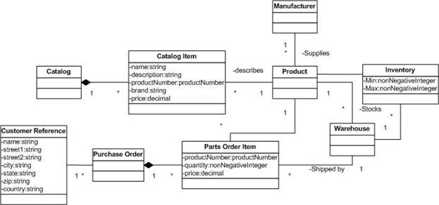
Figure 2: Class Diagram for the Retailer System
The sequence diagrams below describe how the groups of
objects interact with each other.
Use Case 1 maps to the interactions between the invoker
(a retailer provided web page) and the Retailer Service.
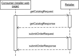
Figure 3: Sequence Diagram for Use Case 1 and the relevant
Web services
Use Case 2 maps to the interactions between the Retailer
Service and Warehouse Services A, B, and C.
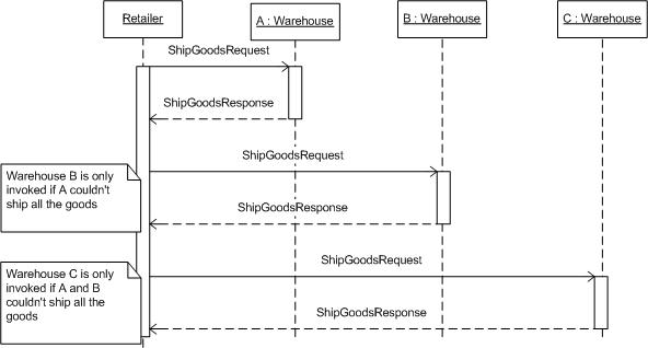
Figure 4: Sequence Diagram for Use Case 2 and the relevant
Web services
Use case 3 maps to the interactions between a warehouse
and a manufacturer (Figure 5Error! Reference source not found.). Use case
4 describes the manufacturer side of this interaction.
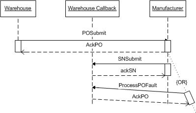
Figure 5: Sequence Diagram for Use Case 3 and the relevant
Web services
This section pertains to the technical design and
implementation of the Manufacturer System of the Basic Profile Sample
Application as specified in the SCM Use Cases v 1 document.
The domain model described in this section relates to the
following use cases outlined in the SCM Use Cases v 1 document, and as
such should be read in conjunction with that document:
·
UC4: Supply Finished Goods
·
UC5: Manufacture Finished Goods
The various types of diagrams (class, sequence,
deployment, etc.) included in this section each provide a different view of the
application, including its interfaces, roles and responsibilities, business
rules, processes as well as the information collected and maintained.
In general this model is implementation independent
except where technical constraints are given as part of the requirements.
|
Term |
Description |
|
Inventory Item |
The details of a product as it relates to availability
(product code, number in stock) |
|
Line Item |
An entry in an order relating to a single product
(product code, required quantity) |
|
Manufacturer |
A party the supplies finished goods to a purchaser. |
|
Product |
A tangible entity that can be sold, finished goods |
|
Purchaser |
Party requesting finished goods. |
|
Purchase Order |
A request from a purchaser to buy products consisting
of one or more line items |
The Manufacturing system supplies finished goods to
warehouses. Requests for finished goods may be fulfilled by the Manufacturer by
supplying from internal stock or, if the required quantity is not available, by
scheduling a production run. Since there could be a considerable time delay
between receiving the order and informing the warehouse of shipment of goods, an
asynchronous processing model is used. This allows a warehouse to proceed on
other business, and allows the Manufacturer to callback to the Warehouse once
the order has been fulfilled.
Below is a conceptual view of an implementation.
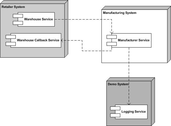
Figure 6: Deployment Diagram for the Manufacturing System
The operations, message types and other relevant
information for each Web service are outlined in the sections below. These
sections specify key details to be defined in the associated WSDL files. The
exact structure of these files is to be resolved as part of the implementation
of the sample application.
The Manufacturer System portion of the sample application
will contain the following web services:
·
Manufacturer Service
Profiles
The web services will be based on the WS-I Basic Profile
V1.0.
Usage Scenarios
The web services in the sample application will rely on
the following usage scenarios (refer to Usage Scenarios document):
·
Synchronous Request/Reply
·
Basic Callback
Operations/Message Types
The following operations/message types should be
supported:
|
Operation |
Msg. Type |
Message |
Parameters |
Type |
|
submitPO |
Input |
POSubmit |
PurchaseOrder |
doc |
|
|
|
|
ConfigurationHeader |
Configuration |
|
|
|
|
StartHeader |
StartHeader |
|
|
Output |
ackPO |
Response |
boolean |
|
|
Fault |
POFault |
|
Client |
|
|
Fault |
ConfigurationFault |
|
Client |
4.4.1.1
submitPO
Description
The purpose of this operation is
to place a purchase order with the manufacturer for finished goods.
PurchaseOrder is a set of line items describing ordered finished goods (see
class diagram).
StartHeader is detailed in the Basic Callback Scenario. This
message header contains a callback location and message identifier to be
retained by the system for sending the shipping notification in the final
request/response. Response is a tacit acknowledgement that the purchase order
was received and validated. If the purchase order is invalid for any reason
(such as invalid schema, invalid quantity, and invalid product number), a
POFault is sent
to the client.
Scenario
The scenario used will be the
initial request/response portion of the Basic Callback Scenario using SOAP over
HTTP.
Message Style
The doc/literal message style
will be used.
The
Manufacturer is defined by a schema and [part of] a WSDL document. The schema
is imported into the types section of the WSDL. As mentioned above, the
Manufacturer WSDL document contains two port types and bindings which together
describe a single Web service type. The ManufacturerPortType and associated
messages and bindings apply to the Manufacturer; the other applies to the
Warehouse.
WSDL
http://www.ws-i.org/SampleApplications/SupplyChainManagement/2002-08/Manufacturer.wsdl
Schema
http://www.ws-i.org/SampleApplications/SupplyChainManagement/2002-08/ManufacturerPO.xsd
Because
the Manufacturer uses and passes showcase configuration information to
Warehouses in a Configuration header, the Manufacturer also imports a
Configuration WSDL and schema. The Configuration Header Fault is described in
the WSDL, and the data types used in the Configuration header and header fault
are described in the schema.
WSDL
http://www.ws-i.org/SampleApplications/SupplyChainManagement/2002-08/Configuration.wsdl
Schema
http://www.ws-i.org/SampleApplications/SupplyChainManagement/2002-08/Configuration.xsd
4.5
Class Diagram
The class diagram below describes the different types of
objects and data elements involved in the manufacturing system and the
relationships that exist among them. Is serves to define the vocabulary of the
system and helps to define the schemas. This is a conceptual diagram and is not
meant to impose any structure on implementations.

Figure 7: Manufacturer Class Diagram
The sequence diagrams below describe how the groups of
objects interact with each other. The diagram below shows the behavior of both
Use Case 4 and Use Case 5. See also the Retailer System, Section 3.6.3.
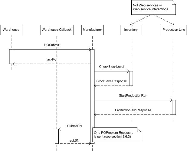
Figure 8: Manufacturer Sequence Diagram
This section pertains to the technical design and
implementation of the Demo System of the Basic Profile Sample Application as
specified in the SCM Use Cases v 1 document.
The domain model described in this section relates to the
following use cases outlined in the SCM Use Cases v 1 document, and as
such should be read in conjunction with that document:
·
UC6: Configure & Run Demo
·
UC7: Log Events
·
UC8: View Events
|
Term |
Description |
|
Demo user |
Person accessing WS-I web site for the purpose of
trying out the sample application. |
|
Configuration |
Settings that allow demo user to direct which
implementations to use in order to purchase goods, manufacture goods,
order parts, etc. |
|
Consumer |
Person accessing the Retailer web site for the purpose
of purchasing consumer electronics. |
Access to the sample application begins at the WS-I.org
web site, which will be referred to as the “WS-I welcome” page. The welcome
page will have a link to another web page hosted by the WS-I.org web site. This
web page shall be called the “sample app” page. The sample app page will
contain a description of the sample application, probably a link for obtaining
the source code, and instructions for demonstrating how the sample application
works. It will also contain one or more buttons or links for getting to the
next web page called the “configuration” page.
The configuration page is where UC6: Configure & Run Demo
begins. This page will present the demo user with a number of configuration
options. These options select implementations for each of the web services in
the sample application.
Having made his/her selections, the demo user clicks on a “start a new demo”
button, which brings the demo user to a web page where he/she can order
products. We will call this the “shopping cart” page. This is where UC1:
Purchase Goods begins. Before the demo user reaches the shopping cart page, a
unique ID is generated to identify the events that are logged as a result of
running the demo. This ID is necessary as it is entirely possible that more
than one person may be running the demo at the same time. Such concurrent usage
would result in log entries that might not make sense when viewed together, but
when filtered based on ID they will illustrate the chain of events typical of a
Supply Chain Management application.
On the shopping cart page, the demo user selects
quantities of products to order, then clicks on a “submit order” button. This
causes the demo system to invoke the Retailer web service. Once the Retailer
has processed the order, the demo system displays the status of the order (i.e.
how many and which products will be shipped). This is referred to as the “order
status” web page. From the order status web page, the demo user may optionally
select to view the events that occurred in the supply chain as a result of
placing an order. This is done on the “track order” web page.
From either the order status page or the track order
page, the demo user may return to the configuration page to start a new demo.
The previous configuration will be presented as a default, but the demo user is
free to change the configuration in order to test interoperability. Note that
it is not possible for the demo user to return to the shopping cart page from
either the order status page or the track order page. In other words, the only
way for the demo user to go back and order more products is to return to the
configuration page first. Figure 9 below presents a graphical representation of
the flow of the sample application.

Figure 9: Sample Application Flow
Figure 10 shows a conceptual view of an implementation.
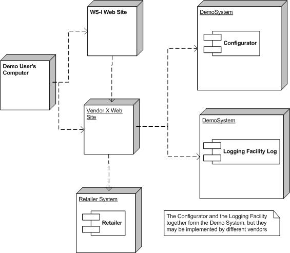
Figure 10: Demo System
Deployment Diagram
This section identifies the Web services which will be
used in the implementation of the previously described architecture of the
sample application. The sample application will be composed of discovered Web
services that utilize the usage patterns as captured in the Basic Profile Usage
Scenarios document, and that conform to the various aspects of the Basic
Profile.
The operations, message types and other relevant
information for each Web service are outlined in the sections below. These
sections specify key details to be defined in the associated WSDL files. The
exact structure of these files is to be resolved as part of the implementation
of the sample application.
The Demo System portion of the sample application will
contain the following web services:
·
Configurator
·
Logging Facility
Profiles
The web services will be based on the WS-I Basic Profile
V1.0.
Usage Scenarios
The web services in the sample application will rely on
the following usage scenarios (refer to Usage Scenarios document):
·
Synchronous Request/Response
·
One-way
Operations/Message
Types
The following operations/message types should be
supported:
|
Operation |
Msg. Type |
Message |
Parameters |
Type |
|
getConfigurationOptions |
Input |
getConfigurationOptions |
Refresh |
Boolean |
|
|
Output |
getConfigurationOptionsResponse |
Response |
sequence of configOptions |
|
|
Fault |
configuratorFailedFault |
|
Server |
Operation Descriptions
5.4.1.1
getConfigurationOptions
Description
The purpose of this operation is
to retrieve a list of all of the implementations registered in the UDDI registry
for each of the web services in the sample application. Note that the
implementation of the Configurator web service may choose to cache the results
of the UDDI look-ups.
Parameters
Refresh – This is a flag which
tells the Configurator web service whether or not the implementations should be
looked up in UDDI. True = perform UDDI look-ups; false = perform UDDI lookup or
return cached results (in other words false is a hint to implementations).
All implementations – This is
what is returned to the caller if there was no error in accessing the UDDI
registry or (optional) internal cache. It is a structure with multiple
sections, one section for each “role” (i.e. web service type) in the sample
application. Each section contains a list of structures, one structure for each
implementation, containing the endpoint URL as well as the vendor name, platform
and language for the registered implementations of that role.
configuratorFailedFault – This is a fault which is raised if there was an
error in accessing the UDDI registry or (optional) internal cache (i.e. no
implementations returned).
Scenario
The scenario used will be
Synchronous Request/Response using SOAP over HTTP.
Message Style
The doc/literal message style
will be used.
The
Configurator is defined by a schema and a WSDL document. The schema is imported
into the types section of the WSDL.
WSDL
http://www.ws-i.org/SampleApplications/SupplyChainManagement/2002-08/Configurator.wsdl
Schema
http://www.ws-i.org/SampleApplications/SupplyChainManagement/2002-08/Configurator.xsd
The
Configurator uses some of the data types defined for the Configuration header.
The schema that defines the Configuration header is therefore imported.
Schema
http://www.ws-i.org/SampleApplications/SupplyChainManagement/2002-08/Configuration.xsd
Operations/Message
Types
The following operations/message types should be
supported:
|
Operation |
Msg. Type |
Message |
Parameters |
Type |
|
logEvent |
Input |
logEvent |
DemoUserID |
string |
|
|
|
|
ServerID |
string |
|
|
|
|
EventDescription |
string |
|
|
|
|
EventId |
string |
|
|
Output |
n/a |
n/a |
n/a |
|
Operation |
Msg. Type |
Message |
Parameters |
Type |
|
getEvents |
Input |
getEvents |
DemoUserID |
string |
|
|
Output |
getEventsResponse |
Response |
Sequence of LogEntry |
|
|
Fault |
RepositoryMissingFault |
|
Server |
Operation Descriptions
5.4.3.1
logEvent
Description
The purpose of this operation is
to log an event that has occurred in one of the other systems in the sample
application.
Parameters
DemoUserID – This is a string
which identifies a demo user. The getEvents operation will retrieve all events
for a specified DemoUserID.
ServerID – This is a string
which identifies the server which requested the event to be logged.
EventDescription – This is a
string which contains a description of the event being logged (e.g. “5 units of
item X shipped from WarehouseB” or “10 units of item Y ordered from
ManufacturerZ”).
Note: it is possible to send
extra XML elements to be logged, which may be ignored if the “processContents”
attribute equals “lax”.
Scenario
The scenario used will be
one-way messaging using SOAP over HTTP.
Message Style
The doc/literal message style
will be used.
5.4.3.2
getEvents
Description
The purpose of this operation is
to retrieve all of the events that have occurred as the result of action taken
by the demo user.
Parameters
DemoUserID – This is a string
which identifies the demo user for whom events are being retrieved.
Response – This is what is
returned to the caller as long as the repository is available. It is a sequence
of structures, where each structure contains the following four items:
Timestamp, ServerID, EventID and EventDescription. The last three
items are exactly the same as those provided as input to the logEvent
operation. The DemoUserID is not returned in the response as it was specified
in the request.
RepositoryMissingFault – This is a fault which is raised if the
repository used to store the log entries is unavailable for whatever reason.
Scenario
The scenario used will be
Synchronous Request/Response using SOAP over HTTP.
Message
The message style used will be
the doc/literal message style.
The
LoggingFacility is defined by a schema and a WSDL document. The schema is
imported into the types section of the WSDL.
WSDL
http://www.ws-i.org/SampleApplications/SupplyChainManagement/2002-08/LoggingFacility.wsdl
Schema
http://www.ws-i.org/SampleApplications/SupplyChainManagement/2002-08/LoggingFacility.xsd
The class diagram below describes the different types of
objects and data elements involved in the demo system and the relationships that
exist among them. Is serves to define the vocabulary of the system and helps to
define the schemas. This is a conceptual diagram and is not meant to impose any
structure on implementations.
Figure 11 below shows the different types of objects in
the Demo system.
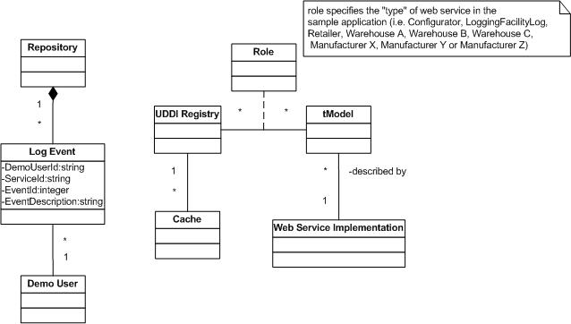
Figure 11:Class Diagram for Demo System
5.6
Sequence Diagrams
The sequence diagrams below describe how the groups of
objects interact with each other. Each diagram shows the behavior of a single
use case.

Figure 12: Sequence Diagram for UC6: Configure & Run Demo
When the demo user requests the demo URL, the
DemoUI class calls the
Configurator class to
get the list of all possible implementations of each and every web service in
the sample application. The Configurator class in turn calls the UDDI
registry to look-up all of the implementations. The
Configurator class may
decide to cache the results of the look-ups.
Having received the list of all possible implementations,
the DemoUI class then
presents the choices to the demo user by displaying the configuration user
interface (web page). The demo user then selects implementation options
(presumably from drop-down list boxes, though other UI widgets may be used) and
submits these selections back to the
DemoUI class
(presumably by pressing a “Submit Choices” button, though other UI widgets may
be used).
When the
DemoUI class receives
the demo user’s selections, it generates an ID (which will be used for
retrieving log events pertaining to the demo user), creates a
Configuration SOAP Header
( which will be passed along to the other systems in the sample application),
and then proceeds to display the product order web page.

Figure 13: Sequence Diagram for UC7: Log Events
This use case is very simple and straight-forward: at
some significant point in the execution of one of the other use cases in the
Supply Chain Management sample application, a web service may decide to log the
fact that some event has occurred in the system as a result of the demo user
interacting with the Retail system. The calling web service collects all the
information to be logged, and sends it to the logging facility using a one-way
call (which is why the sequence diagram does not show a return from the logging
facility back to the calling web service).
When the logging facility receives the request to log an
event, it validates the request, and if the request is valid, proceeds to save
the information sent to it in the log that it maintains. If the request is
invalid, the logging facility will log the reason for the invalid request (e.g.
message does not conform to schema). Of course, before saving a new entry in
the log, the logging facility should check that the repository which it is using
for storing the log entries is available. Different implementations will
provide different qualities of service, but it is assumed that log entries will
have a minimum life-span of one hour.
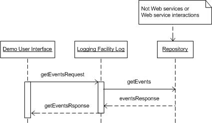
Figure 14: Sequence Diagram for UC8: View Events
The view events use case is initiated by the demo user
navigating to the appropriate place in the user interface. This can be either a
link or a button. Once the demo user has clicked on the button (or hyper-text),
the user interface calls the logging facility to retrieve the log entries
associated with the current demo user.
The logging facility accesses its repository of log
entries, extracts the appropriate ones, and returns them to the user interface,
which then displays them to the demo user. If for some reason the repository of
log entries cannot be accessed, then a fault is returned to the user interface,
and error message is displayed to the demo user.
6
Design Aspects of the Basic Sample Application
This
section describes the technical design aspects of the Basic Sample Application.
The technical descriptions of the Web services and their associated schemas are
included here, as are the fundamentals of the showcase User Interface, logging
of events, fixed sample data, and the advertisement of sample Web services in
UDDI.
Implementations of WS-I Basic Sample Application Web services are provided by
individual WS-I members. Some members may host live instances of their Web
services. WS-I provides access to these hosted instances through a showcase
version of the Basic Sample Application that can be launched from the WS-I Web
site.
One or
more front ends to the Basic Sample Application may be implemented by WS-I
member companies. These contributors may host live instances of their front
ends which can be accessed from the the WS-I interoperability showcase.
The sample
Web services are designed around a simple transaction model that the front ends
must enforce. The front end assigns a unique id to each user of the demo every
time a configuration is chosen. The front end is required to force the user to
the configuration selection, and generation of a new unique id, each time a new
order is to be made, as this defines a transaction boundary. After the user
concludes submission of an order, the events logged for that request can be
viewed through the front end. But if when the user wants to try a different
order, s/he must start by selecting a configuration, and thus be assigned a new
unique ID. It’s suggested, but not required, that the previous configuration be
retained for the same user so that incremental changes can be made when starting
a new transaction.
The front
end invokes a Configurator Web service to obtain the list of Web service
instance choices. In the WS-I interoperability showcase, this list of choices
is obtained from the UDDI business registry. The showcase further offers a
choice of Configurator Web service to use. When the user has chosen a
configuration and has elected to proceed with constructing an order, the front
end retrieves the product catalog from the chosen Retailer Web service. The
chosen Retailer Web service is also used to submit the order the user
constructs. Finally, the front end uses the chosen LoggingFacility Web service
to obtain the log events associated with the transaction’s unique ID. These log
event provide evidence of progress through the supply chain.
The Basic
Sample Application is composed of a set of Web service implementations with a
User Interface front end. The data types used by the sample application are
contained in a set of xml schemas, and the Web services are described using WSDL
1.1. All WSDL documents described here for the WS-I Basic Sample Application
are common across implementations, containing types, message, portType and
binding descriptions. Endpoints for implementations of WS-I Sample Web services
are advertised in UDDI, as described below, and the service and port
descriptions are thus not specified in the WS-I WSDL documents.
As
described in previous sections of this document, an attempt was made to define
an application in an easily understandable application domain that has many
opportunities for simplification of the business logic so that the sample can
focus on interoperability. The main goal of the Basic Sample Application is to
demonstrate interoperability among Web services, based on the set of
specifications defined by the Basic Profile 1.0. As shown in the table below,
the sample schemas and WSDL employ a diverse set of styles, and offer valid
alternative techniques for describing the Web services. For example, the WSDL
descriptions of the sample Web services employ different styles of specifying
SOAP Action, adopt rpc/literal and document/literal styles, use obscure data
types in xml schema where possible, specify headers for application meta-data,
and use different naming conventions. All of these differences and combinations
of differences yield a higher degree of confidence in the interoperability
capabilities of different kinds of Web services.
|
|
Retailer |
Warehouse |
WH Callback |
Manufacturer |
Logging
Facility |
Configurator |
|
Usage Scenario |
Request/
Response |
Request/
Response |
Basic Callback;
Request/Response |
Basic Callback; Request/Response |
One-way;
Request/Response |
Request/ Response |
|
Style |
Rpc/literal |
Rpc/literal |
Doc/literal |
Doc/literal |
Doc/literal |
Doc/literal |
|
Header |
Yes |
Yes |
Yes |
Yes |
No |
No |
|
Data types |
nonnegative
Integer
decimal
string
integer
normalizedString
NMTOKEN
anyURI |
normalizedString
nonnegative
Integer
unsignedShort
boolean
NMTOKEN
anyURI
string |
nonnegative
Integer
unsignedShort
float
string
normalizedString
NMTOKEN
anyURI |
string
float
normalizedString
nonnegative
Integer
unsignedShort
NMTOKEN |
string
dateTime
NMTOKEN |
boolean
string
NMTOKEN
anyURI |
|
Attribute |
Yes |
Yes |
Yes |
Yes |
No |
Yes |
|
SOAP Action |
Empty string |
WSDL tns |
None |
None |
Empty string |
WSDL tns + operation |
|
Naming |
Mixed |
Start with upper case |
Mixed |
Mixed |
Start with upper case |
Start with lower case |
All Basic
Sample Application schemas and WSDL documents are accessible from the WS-I Web
site. The URLs used are the same as the namespace associated with each
document.
The interaction between the Warehouse and the
Manufacturer, whereby the Warehouse submits a purchase order to a Manufacturer
to replenish its stock on hand, is implemented via the Basic Callback usage
scenario. This usage scenario is an asynchronous message exchange between two
Web services using a pair of synchronous request/response message exchanges.
The implementation of the Basic Callback usage scenario requires some mechanism
for correlating a final request/response with its corresponding initial
request/response. It also requires some mechanism for the consumer (i.e. the
initiator of the initial request/response) to convey the callback endpoint to
the provider (i.e. the recipient of the initial request/response).
This is
achieved by the consumer allocating an identifier and passing that identifier in
a SOAP header of the initial request, identified as the “StartHeader”. The
identifier is then passed back in the SOAP header of the callback, identified as
the “CallbackHeader”. The identifier is not required on the two
“acknowledgement” replies, as these are part of the respective synchronous
request/response interactions. In order to inform the provider of the callback
location, the consumer includes the URL of the callback endpoint in the
“StartHeader” of the request.
Basic
Sample Application Web services are advertised in the UDDI Business Registry
(UBR) to enable discovery of alternative implementations. The advertised
descriptions of these web services follow the guidelines set forth in the
Using WSDL in a UDDI Registry, Version 1.08 Best Practice document with
additional data elements that distinguish the contents of the sample application
as a showcase for Web service interoperability.
The UBR is
a public UDDI registry that has multiple nodes, offered by IBM, Microsoft, NTT,
and SAP. To advertise something in UDDI a publisher must first obtain
publishing credentials at one of the nodes. Once publishing credentials have
been obtained they are used to advertise Web services at the node granting the
credentials. Because registered data is replicated between these nodes,
discovery can be performed at any of the registry’s nodes.
The nodes
in the UBR provide access to the registry programmatically and over the Web.
Publishing credentials are requested using the Web interface. WS-I content is
advertised using the programmatic interface.
Publishing
credentials can be requested at one of the following UBR nodes:
UDDI SOAP
messages for advertisement may be sent to one of the following URLs:
Each Basic
Sample Application Web service type is captured in a WSDL document that contains
the corresponding wsdl:message, wsdl:portType, and wsdl:binding elements but
does not contain the wsdl:service and wsdl:port elements since they are specific
to a deployed Web service. These WSDL documents are accessible using HTTP GET at
a site provided by WS-I.
A UDDI
tModel is published for each of these Web service type descriptions. Each
tModel refers to the Web service type WSDL document in its overviewURL
element. The URL includes the xpointer-based fragment identifier for the
applicable named wsdl:binding. Each tModel is categorized with the
soapSpec and wsdlSpec types from the uddi-org:types category
system.
WS-I has a
category system named ws-i-org:conformsTo:2002_12 that is used to self-certify
conformance with the WS-I profiles. A tModel for the WS-I Sample Application
should be given a category value of “http://ws-i.org/profiles/basic/1.0” which
indicates compliance with the Basic Profile.
An example
save_tModel operation containing a tModel element that can be used to convey a
description of a conformant Web service type is described below. The tModelKey
is a zero length string that is assigned by the UDDI publication service the
first time the tModel is published. The assigned tModelKey is contained in the
tModelDetail that is returned from the save. Subsequent (re)publishes of the
tModel must contain the actual tModelKey. Note that to publish a tModel one is
required to obtain a UDDI authentication token using the get_authToken
UDDI message and insert this into the authInfo element in the save message.
<save_tModel
generic="2.0" xmlns="urn:uddi-org:api">
<authInfo>Authorization token
returned from get_authToken</authToken>
<tModel
tModelKey="key
assigned by the registry">
<name>ws-i-org:SampleApplications:SupplyChainManagement:Name of Web
service type</name>
<description>Web service type for ...</description>
<overviewDoc>
<description>WSDL for ... Web service type</description>
<overviewURL>
URL of the Web service type WSDL
</overviewURL>
</overviewDoc>
<categoryBag>
<keyedReference
tModelKey="UUID:C1ACF26D-9672-4404-9D70-39B756E62AB4"
keyValue="wsdlSpec" keyName="types:wsdlSpec" />
<keyedReference
tModelKey="UUID:C1ACF26D-9672-4404-9D70-39B756E62AB4"
keyValue="soapSpec" keyName="types:soapSpec" />
<keyedReference
tModelKey="uuid:65719168-72c6-3f29-8c20-62defb0961c0"
keyValue="http://ws-i.org/profiles/basic/1.0"
keyName="ws-i-conformance:basicProfile" />
</categoryBag>
</tModel>
</save_tModel>
The
tModelKeys assigned to the WS-I Basic Sample Application Web service types are:
Retailer:
UUID:44599540-CC06-11D6-9D4F-000629DC0A53
Warehouse:
UUID:79CF57F0-CC06-11D6-9D4F-000629DC0A53
Manufacturer:
UUID:AD04EEA0-CC06-11D6-9D4F-000629DC0A53
LoggingFacility:
UUID:FE462140-CC05-11D6-9D4F-000629DC0A53
Configurator:
UUID:C5FE2BC0-CC05-11D6-9D4F-000629DC0A53
A UDDI
businessService and bindingTemplate pair is published for each Web service
instance that implements a Web service type described by a tModel. The
bindingTemplate corresponds to a wsdl:port element. UDDI businessService
elements and their contained bindingTemplates are published within a
businessEntity. You are required to have publishing credentials, as described
above, to publish any of these entities.
Each
bindingTemplate contains an accessPoint element. The end point where the Web
service instance can be reached is placed in this element. Information about
the sample Web service implementation is captured in name/value pairs in the
bindingTemplate’s instanceParms to assist the demo user in choosing
implementations to demonstrate. Such information is irrelevant for Web services
that are not part of the WS-I Basic Sample Application. The bindingTemplate
references a tModel for one of the conformant Basic Sample Application's Web
service types in its tModelInstanceDetails, indicating that the Web service
instance implements the Web service type.
Some of
the Basic Sample Application Web services apply to a certain role in the Basic
Sample Application. These roles are captured in the categoryBag of the
businessService using the UDDI General Keywords category system, as shown in the
example below.
An example
save_service operation for a showcase Web service implementation described with
the UDDI businessService and bindingTemplate elements is shown below. Note that
to publish any of these entities one is required to obtain an authentication
token using the get_authToken UDDI operation and use this in the save message.
The serviceKey and bindingKey are zero length strings the first time these
entities are saved. A serviceKey is assigned to the new businessService and a
bindingKey is assigned to the new bindingTemplate. These are both contained in
the serviceDetail returned from the save. Subsequent (re)publishing of the
businessService and/or bindingTemplate must contain the assigned keys.
<save_service generic="2.0" xmlns="urn:uddi-org:api">
<authInfo>Authorization token
returned from get_authToken</authToken>
<businessService
businessKey="businessKey
for the outer businessEntity">
<name>Name
of business & name of the Web service</name>
<bindingTemplates>
<bindingTemplate bindingKey="">
<accessPoint>
end point URL for the Web service implementation
</accessPoint>
<tModelInstanceDetails>
<!--The tModelKey(s) captured in the tModelInstanceInfo
elements establish the technical fingerprint of the Web
service -->
<tModelInstanceInfo
tModelKey="key assigned to the Web service type tModel">
<instanceDetails>
<instanceParms>
implPlatform=WebSphereV4;implOS=AIX;implLanguage=Java
</instanceparms>
</instanceDetails>
</tModelInstanceInfo>
</tModelInstanceDetails>
<bindingTemplate>
</bindingTemplates>
<categoryBag>
<keyedReference
tModelKey="uuid:A035A07C-F362-44dd-8F95-E2B134BF43B4"
keyValue="asia"
keyName="ws-i:sampleRole:warehouse" />
</categoryBag>
</businessService>
</save_service>
Implementations of Basic Sample Application Web services will only appear in the
WS-I Interoperability Showcase if their owning businessEntities have reciprocal
business relationships with WS-I. Both WS-I and each publisher of the Web
service implementations must save identical peer-to-peer publisherAssertions in
UDDI for the relationships to form. This is accomplished using the
set_publisherAssertion API as demonstrated below.
<set_publisherAssertion generic="2.0"
xmlns="urn:uddi-org:api">
<authInfo>Authorization
token returned from get_authToken</authToken>
<publisherAssertion>
<fromKey>EE7A7A30-F67C-11D6-B618-00629DC0A53</fromKey>
<toKey>Business
key of the implementation’s businessEntity</toKey>
<keyedReference keyName=”peer-peer” keyValue=”peer-peer”
tModelKey=”uuid:807A2C6A-EE22-470D-ADC7-E0424A337C03”/>
</publisherAssertion>
</setPublisherAssertion>
The WS-I
Basic Sample Application has two Web service types that are reused for different
roles in the Sample Application. There can be 3 distinct Warehouses and 3
distinct Manufacturers. To be able to determine the role that the Web service
instance is adopting, businessServices for these Sample Web service instances
are categorized with specific values, using the UDDI general keywords category
system (UUID:A035A07C-F362-44DD-8F95-E2B134BF43B4). Both the keyName and the
keyValue are significant in any keyedReference associated with the general
keywords category system.
Warehouses
are assigned a categorization that designates a geographical area.
Warehouse A: keyValue=NorthAmerica keyName=ws-i:sampleRole:warehouse
Warehouse B: keyValue=Europe
keyName=ws-i:sampleRole:warehouse
Warehouse C: keyValue=Asia
keyName=ws-i:sampleRole:warehouse
Manufacturers are assigned a categorization that designates a brand.
Manufacturer A: keyValue=BrandA
keyName=ws-i:sampleRole:manufacturer
Manufacturer B: keyValue=BrandB
keyName=ws-i:sampleRole:manufacturer
Manufacturer C: keyValue=BrandC keyName=ws-i:sampleRole:manufacturer
Any other categorizations on
other sample app Web services will be ignored.
Interactions with Web services
involved in the supply chain are recorded using events in the Sample Application
Logging Facility where they can be retrieved and used to chart progress through
the supply chain. These events provide evidence of invocations of Sample
Application web services. Events are recorded at the start of each web service
operation, and at each exit point.
Use cases for the Sample Application are used to denote
the points at which an event is logged. Service IDs record the Web service role
that is processing the operation and the name of the operation. EventIDs refer
to the Use Case step to indicate where in the Sample Application Use Cases the
event originates from. The event descriptions provide functional context for
the events.
|
EventID |
ServiceID |
EventDescription |
What it
means |
|
UC1-5 |
Retailer.submitOrder |
Order placed by
<customer id> for <product number 1>, <product number n>. |
Start of the
Retailer submitOrder operation. |
|
UC1-9 |
Retailer.submitOrder |
Processing of the
order from <customer id> has finished normally. |
Completion of the
Retailer submitOrder operation. |
|
UC1-ALT1-1 |
Retailer.submitOrder |
Order placed by
<customer id> is rejected as <product n> is not a valid product and
processing has terminated. |
Invalid product
encountered in the Retailer submitOrder operation. |
|
UC1-ALT2-1 |
Retailer.submitOrder |
There is no
availability for any products in the order placed by <customer id> and
processing is terminated. |
Unable to fulfill
any of the order in Retailer submitOrder operation. |
|
UC2-2-1 |
Warehouse<n>.ShipGoods |
Warehouse<n> will
determine its ability to ship <product number 1>, … <product number n> |
Start of the
Warehouse ShipGoods operation. |
|
UC2-2-2 |
Warehouse<n>.ShipGoods |
Warehouse<n> is
able to ship <product number 1>, … <product number n> and is unable to
ship <product number 1x>, … <product number nx> |
Completion of the
Warehouse ShipGoods operation. |
|
UC3-3 |
Manufacturer<n>.submitPO |
Manufacturer<n> is
replenishing stock for <product number> |
Start of the
Manufacturer submitPO operation. |
|
UC3-7-1 |
Warehouse<n>.submitSN |
Warehouse<n> has
received notice that <product number> has been shipped by
Manufacturer<n> |
Start of the
Warehouse submitSN operation indicating the manufacturer has has shipped
stock to the warehouse. |
|
UC3-7-3 |
Warehouse<n>submitSN |
Warehouse<n> is
unable to correlate the shipment of <product number> with a pending
replenishment request. |
Correlation error
encountered attempting to match the shipment with a pending
replenishment request. |
|
UC3-7-4 |
Warehouse<n>errorPO |
Warehouse<n> is
unable to correlate the notification of a shipping error with a pending
replenishment request. |
Correlation error
encountered attempting to match the manufacturing error with a pending
replenishment request. |
|
UC3-ALT1-1 |
Manufacturer<n>.submitPO |
Invalid
replenishment request received by Manufacturer<n> for <product number> |
Manufacturer is
unable to process the purchase order due to invalid or insufficient
data. |
|
UC3-7-2 |
Warehouse<n>.submitSN |
Warehouse<n> has
replenished stock for product <product number> |
Completion of the
submitSN operation by a Warehouse indicating stock is replenished. |
|
UC4-1 |
Manufacturer<n>.submitPO |
Manufacturer<n> is
shipping product <product number> from existing inventory |
Completion of
asynchronous submitPO operation by the Manufacturer indicating the
replenishment request was satisfied from existing stock. |
|
UC5-5 |
Manufacturer<n>.submitPO |
Manufacturer<n> has
produced additional units of <product number> and is shipping <n> units. |
Completion of
asynchronous submitPO operation by the Manufacturer indicating more
product was manufactured before the replenishment request could be
satisfied. |
6.6
State Data Used by the Basic Sample Application
Demonstrating interoperability in an application such as the sample Supply Chain
Application requires that each identical request results in an identical
response, both from a data, and an execution sequence point of view. To
accomplish this, the Sample Retailer, Warehouse, and Manufacturer Web services
operate with a fixed set of data that is reset for each new order request.
The
Retailer keeps track of the Product Catalog. The Product Catalog contains a
fixed set of products, with identifying information about them. The Product
Catalog is defined in the table below.
|
Product Number |
Name |
Brand |
Description |
Category |
Price |
|
605001 |
TV,
BrandA |
BrandA |
24”, color, advanced velocity scan modulated |
TV |
299.95 |
|
605002 |
TV,
BrandB |
BrandB |
32”, super slim flat panel plasma |
TV |
1499.99 |
|
605003 |
TV,
BrandC |
BrandC |
50”, plasma display |
TV |
5725.98 |
|
605004 |
VCR, BrandA |
BrandA |
S-VHS |
VCR |
199.95 |
|
605005 |
VCR, BrandB |
BrandB |
HiFi, S—VHS |
VCR |
400.00 |
|
605006 |
VCR, BrandC |
BrandC |
S-VHS, MINDY |
VCR |
949.99 |
|
605007 |
DVD, BrandA |
BrandA |
DVD-Player w/built-in Dolby Digital decoder |
DVD |
100.00 |
|
605008 |
DVD, BrandB |
BrandB |
Plays DVD-Video discs, CDs, stereo and music |
DVD |
200.00 |
|
605009 |
DVD, BrandC |
BrandC |
DVD
Player with SmoothSlow forward/reverse; Digital Video Enhancer; DVD/CD
test; Custom parental control (20-disc); Digital cinema sound modes |
DVD |
250.00 |
|
605010 |
TV,
Brand4 |
Brand4 |
Designated invalid product code that is allowed to appear in the
catalog, but is unable to be ordered |
TV |
149.99 |
The fixed
data used by Warehouses and Manufacturers is described in the table below.
|
|
WH A |
WH B |
WH C |
Mfg A |
Mfg B |
Mfg C |
|
Product 605001 |
|
|
|
|
|
|
|
Stock |
10 |
30 |
45 |
10 |
|
|
|
Minimum |
5 |
5 |
5 |
5 |
|
|
|
Maximum |
25 |
55 |
55 |
25 |
|
|
|
Product 605002 |
|
|
|
|
|
|
|
Stock |
7 |
10 |
20 |
|
5 |
|
|
Minimum |
4 |
4 |
4 |
|
5 |
|
|
Maximum |
20 |
20 |
20 |
|
10 |
|
|
Product 605003 |
|
|
|
|
|
|
|
Stock |
15 |
15 |
15 |
|
|
15 |
|
Minimum |
10 |
10 |
10 |
|
|
10 |
|
Maximum |
50 |
50 |
50 |
|
|
50 |
|
Product 605004 |
|
|
|
|
|
|
|
Stock |
55 |
70 |
11 |
70 |
|
|
|
Minimum |
10 |
10 |
10 |
5 |
|
|
|
Maximum |
70 |
70 |
70 |
100 |
|
|
|
Product 605005 |
|
|
|
|
|
|
|
Stock |
10 |
10 |
10 |
|
10 |
|
|
Minimum |
5 |
5 |
5 |
|
5 |
|
|
Maximum |
10 |
10 |
10 |
|
10 |
|
|
Product 605006 |
|
|
|
|
|
|
|
Stock |
20 |
20 |
20 |
|
|
20 |
|
Minimum |
5 |
5 |
5 |
|
|
5 |
|
Maximum |
20 |
20 |
20 |
|
|
20 |
|
Product 605007 |
|
|
|
|
|
|
|
Stock |
70 |
30 |
85 |
70 |
|
|
|
Minimum |
30 |
30 |
30 |
30 |
|
|
|
Maximum |
100 |
100 |
100 |
100 |
|
|
|
Product 605008 |
|
|
|
|
|
|
|
Stock |
25 |
35 |
45 |
|
35 |
|
|
Minimum |
10 |
10 |
10 |
|
10 |
|
|
Maximum |
50 |
50 |
50 |
|
50 |
|
|
Product 605009 |
|
|
|
|
|
|
|
Stock |
20 |
30 |
40 |
|
|
40 |
|
Minimum |
20 |
20 |
20 |
|
|
20 |
|
Maximum |
50 |
50 |
50 |
|
|
50 |