This chapter describes the overall Microsoft®
Systems
Architecture
Internet
Data
Center
network design. It
provides an overview of architectural elements, such as routers and switches, as
well as Web infrastructure design and components. It also discusses the
configuration of the Microsoft Windows® 2000 Server operating system and
traffic between virtual local area networks (VLANs). Details about the specific
aspects of the
Internet
Data
Center
design are included
in subsequent chapters of this guide.
This chapter is
intended for networking professionals involved in the planning and design of
network infrastructure for an Internet Data
Center.
All networking
technologies in this chapter have been designed and specified to adhere to the
design goals laid out below. Whilst
this creates a highly available configuration with no single point of failure,
it is expected that the configuration will be customized to meet business
requirements.
Networking
infrastructure planning and design will typical require the involvement of
specialist resources and often need the involvement of relevant network
vendor(s).
The key architectural elements of the
Internet
Data
Center
network include
clients, perimeter routers, load balancers, cloned front-end Web servers,
multilayer switches, firewalls, infrastructure servers and back-end database and
management systems. This section focuses on the logical components that provide
an infrastructure that is scalable, available, secure, and manageable.
In the Internet Data Center environment, clients issue requests
to a service name, which represents the application being delivered to the
client. The end-user system and the client software have no knowledge about the
inner workings of the system that delivers the service. The end user typically
types the first URL, for example, http://www.blueyonderairlines.com, and
then either clicks hyperlinks or completes forms on Web pages to navigate deeper
into the site. In business-to-business (B2B) scenarios, the client
is another server computer at the partner’s site that runs an automated process
and connects to exposed services on the local Internet Data Center B2B server.
An example would be two servers running Microsoft BizTalk™ Server that exchange
documents during the supply chain management process.
Perimeter routers
connect the infrastructure to the Internet service provider (ISP) networks. For
high-end Web-business environments, full redundancy should be considered. Full
redundancy requires at least two perimeter routers, with each router connected
to a different ISP. This implementation provides fault tolerance and traffic
aggregation. The routers should run Border Gateway Protocol (BGP) to ensure
proper and fast routing. Most routers are capable of enforcing traffic policies,
which should be used to help secure a perimeter network and add an additional
level of security for the internal network.
Load Balancing is
used to distribute load among multiple servers and provide for high
availability. In the
Internet
Data
Center
design, load
balancing is used for the front-end Web systems and the perimeter firewalls.
This design provides both resilience and scalability for the most important
network elements.
Internet facing
(front-end) servers are the collection of servers that provide the core Web
services, such as HTTP and HTTPS, to Internet clients or servers. Developers
usually group these front-end systems into sets of identical systems called
clones. The clones run the same software and have access to the same Web
content, HTML files, ASPs, scripts, and so forth, either through content
replication or from a highly available file share. By load balancing the
requests across a set of clones, and by detecting and separating a failed clone
from the other working clones, you can achieve high degrees of scalability and
availability. Details on how the
Internet
Data
Center
design implements
these technologies at the front-end Web appear later in this
chapter.
The design can
be implemented with multiple physical devices or two multilayer switches. The
Internet
Data
Center
configuration uses two multilayer
switches to maintain simplicity, manageability, and flexibility. The switches
are partitioned as multiple logical Layer 2 devices. VLANs are created and
spanned over both switches to provide hardware fault tolerance. The servers are
configured with two teamed network adapters and connected to the same VLAN on
each physical switch. The traffic between VLANs is routed by using the internal
router in each core switch and controlled by using access control lists (ACLs).
Some network and security analysts might consider it less secure to put the
external and internal networks on the same physical device. However, that would
only be the case if the physical device were incorrectly configured. Most
multi-layer devices are very secure, and if configured properly, do not add to
the security risk. If this remains a concern, perimeter networks can simply be
moved off the core switches and onto physically separate
switches.
A firewall is a mechanism for controlling the flow of data
between two parts of a network that are at different levels of trust. The design
of the firewall solution in the Internet
Data
Center
architecture is described in Chapter 3, “Firewall
Design.”
The
infrastructure VLAN was created to host domain controllers running
Windows 2000 with Active Directory™ directory service and DNS. Depending on
the application design, the infrastructure VLAN can also be used to host servers
running components and business objects (for example, BizTalk Server 2000 or
Message Queuing). If the application is designed to support three tiers, the
infrastructure network can host application logic and services. Most
applications are designed logically as three-tiered systems, but this design
also supports a physical two-tiered application allowing Web servers to
communicate directly with the servers running SQL Server.
Back-end
systems are either the actual data stores that maintain application data, or
they enable connectivity to other systems that maintain data resources. Data can
be stored in flat files or in database systems such as SQL Server 2000 back-end
systems. The database systems are more challenging to scale and make highly
available, primarily due to the data and state they must maintain.
For increased
availability, a cluster supports each partition. These clusters typically
consist of two nodes with access to common, replicated, or RAID-protected
storage. When the service on one node fails, the other node takes over the
partition and offers the service.
The corporate
connection is the link between the Internet
Data
Center
and the internal network used for the enterprise. Even though a full discussion
of the corporate connection is out of the scope of this chapter, connectivity
requirements related to management and/or reporting may arise. How this
connection is configured is very important because it must not be allowed to
impact the security, reliability, or availability of the data center
architecture. Details of the options available for this connection and how the
Internet Data Center design implements it appear later
in this chapter.
The Internet Data Center design is flexible because it uses
VLAN technologies to separate servers and communication traffic. The core VLANs
created in support of the different server traffic requirements consist of DMZ,
infrastructure, and data/management VLANs (shown as Ethernet network pipes in
the following figure).
The DMZ,
infrastructure, and data and management VLANs are the core VLANs for the design
decisions made in the architecture. The DMZ network consists of multi-homed Web
servers and the external DNS servers that users can query directly from the
Internet through the Internet perimeter firewalls. The DMZ is in fact made up of
three VLANs, to allow for traffic isolation,, but for now we will simply refer
to all three as the DMZ VLAN. The data and management VLAN is comprised of the
SQL Server 2000 database servers and other required management and backup
servers. The infrastructure VLAN contains servers that provide services required
by the DMZ network or data and management VLANs, for example, Active Directory
and DNS. Additional services will be added here as the application for the
Internet Data Center is developed. For example,
Microsoft Commerce Server 2000 and BizTalk Server details are provided as part
of the BizTalk and Commerce Server design chapters later in this guide.
The following
diagram depicts the network segmentation and inter-communication in the form of
a logical architecture diagram.

Figure 1.
Overview of the base Internet Data Center
design
Before going
into the details of each of the components within the VLANs, it is useful to
consider why the architecture looks the way it does. The following sections
discuss some aspects of the design.
The VLAN architecture allows traffic flow to be managed
efficiently by creating a series of protected security devices to which rules
and policies can be applied.
The current
Internet Data Center architecture completely locks down
all Web servers by using a Web server security policy and Active Directory
organizational units. For details about the implementation of Active Directory
organizational units, refer to Chapter 5, "Security Design.”
Since the Web
servers in the Internet Data Center architecture
are multi-homed (two network interface cards, or NICs), architects were
concerned about hackers gaining access to the production network through the
back-end network interface card (NIC). The architecture design adds another
layer of protection by separating the DMZ VLAN from the rest of the production
VLANs by placing a firewall directly between the internal network interface of
all the servers in the DMZ VLAN and the other internal VLANs. All traffic from
the DMZ VLAN that flows to the servers that are in the production VLANs must go
through the firewall first. If hackers did gain access to a Web server, they
would still need to beat the security configuration of the internal firewall
before they could damage data.
Having a
separate data and management VLAN allows the most important servers (normally
the servers running SQL Server) to be placed behind two sets of protection.
First, the Internet Data Center architecture
uses stateful inspection and firewall access control lists (ACLs) to control the
communication of TCP and UDP ports between servers in the DMZ VLAN and servers
in the data and management VLAN. Second, the design uses VLAN technologies and
additional access control lists on the switch that can be configured to control
the communication of TCP and UDP ports between the infrastructure VLAN and the
data and management VLAN.
Network
availability can be achieved by providing redundancy at every level and by using
automatic failover. Two network devices are implemented within each layer of the
architecture to provide high availability at the network level. Duplicate
routers, switches, and firewalls are implemented to maintain availability
throughout the network. There is no single device in the design that would bring
the site down. If the firewall fails, a backup firewall takes over. If one
switch fails, another one takes on full load until the first one is repaired. If
a Web server’s network adapter fails, another NIC becomes active automatically
with no impact on traffic flow. If a complete Web server fails it can be taken
offline, repaired, and added back into Web farm without any impact on
production. The database partitions on the SQL Server computers are protected as
part of a SQL Server database cluster.
Network traffic is becoming more and more unpredictable.
The old 80/20 rule held that 80 percent of network traffic was limited to the
workgroup, with only 20 percent involving the Internet. But with the increasing
use of e-business systems, the current ratio is closer to 50/50. If trends
continue the ratio may invert to 20/80, significantly increasing backbone
traffic. As the Internet backbone bandwidth increases, it will increase network
demand on the e-commerce sites.
Technological development is moving fast to provide
technology that will ease the pressures in e-commerce networks and provide a
path for upgrade to higher bandwidth requirements. The network design should
include new technologies, such as Layer 2 and Layer 3 devices that switch and
route traffic at wire speed. Modular and stackable switches offer port density
and port speeds up to 100 megabits per second (Mbps). These devices also provide
solutions for e-commerce data centers where the switch can be stacked with
gigabit Ethernet (1000-Mbps) links, and provide thousands of high-speed ports.
Bandwidth
aggregation for servers is available through multiple adapter technologies,
which eliminate server bottlenecks by allowing incremental increases in
bandwidth between a server and a switch. These technologies enable high-speed
transmissions that extend the capacity of the physical medium.
To simplify
the Internet Data Center design, all
unnecessary VLANs have been eliminated and multi-homing is used only when
absolutely necessary. In particular, the design has no separate management VLAN
because this would require that both the infrastructure, management and the data
servers be multi-homed.
By placing all
of the management servers where they have the most impact, the Internet Data Center design eliminates the complexity
and addresses some of the traffic and security concerns that having a separate
management network would introduce. However, the design does have multi-homed
Web servers, because it is important to segment inside and outside traffic with
separate VLANs and eliminate NetBIOS over TCP/IP on the outside interface. In
other words,
the Internet Data Center design does
incorporate complexity when it is justified by a significant gain in
availability, reliability, management, or security.
The connection
point between the Internet Data Center network and
the outside world is the router. These perimeter routers (also known as border
or edge routers) must enable the main services of any network design: security,
high availability, and scalability.
In the
Internet Data Center design, the perimeter routers
operating system security services provide the first step to a secure front end
to the network. This is achieved by using the extended ACLs of the routers to
secure the network traffic allowed onto the perimeter network.
For
reliability and availability, the network uses a high availability protocol to
ensure that this router configuration is fault tolerant. The Border Gateway
Protocol (BGP) provides routing availability and load-balancing capability. The
perimeter routers also provide a set of QoS (Quality of Service) features that
could be used to improve the availability of user sessions during times of peak
load on the network.
The Internet Data Center design uses perimeter routing
to:
·
Implement redundant routers for
the Internet Data Center architecture
to eliminate the single point of failure. Connect each router to a different ISP
connection for maximum availability.
·
Supply BGP capability to fully
use ISP routing information. This is critical in a multiple ISP scenario, where
network load balancing and policing routing is important. In addition, routers
with BGP capability are recommended for scalability.
Note: This requires the ability to
obtain an Autonomous System Number (ASN)
·
Create multiple paths through the
network infrastructure for higher availability and make use of these paths
to allow for load sharing and higher scalability through routing-protocol load
balancing.
·
Use external BGP routes (EBGP
on perimeter routers) for the propagation of local IP network routes to the
interconnected ISPs. This allows path discovery to the e-commerce site. By
exchanging full Internet BGP routes with all ISPs, the perimeter routers can
determine the best return path and offer the quickest response to the customer.
·
Apply tight extended ACLs from
the inbound interfaces to the perimeter routers. These ACLs should only allow
traffic that is relevant to the e-commerce site.
·
Deny any traffic destined to the
routers by using ACLs, but allow BGP traffic that uses TCP/179 if the
packets arrive from adjacent ISP routers.
·
Prevent Internet Control Message
Protocol (ICMP) packets from being transmitted through the router, because
support of the ping command, and similar capabilities, can lead to
attacks.
·
Install a spoofing ACL to
prevent traffic that is structured to appear as if it were sourced from the data
center from actually entering the data center. This ensures that traffic with a
source address in the perimeter network really does originate there and not from
the outside.
·
Secure the console interface on
the routers themselves with user names and passwords. One method is to use
Remote Access Dial-In User Service (RADIUS), to authenticate and account for
those administrators who log on to the router consoles. Use Kerberos
authentication or Secure Shell (SSH) to access the router
console.
·
Allow only TCP/80 (HTTP), TCP/443
(SSL), TCP/25, and UDP/53 (DNS) to enter the data center. It is possible
that customized applications that were developed to run on top of the Internet Data Center design will require additional
protocols to allow the clients to perform additional actions, such as using File
Transfer Protocol (FTP). If this is the case, ensure that this does not violate
the corporate policy and then adjust the port configurations
accordingly.
The second
router configuration in the Internet
Data
Center
design was created to provide a secure connection to the architecture from
remote locations. These connections are primarily for access to the management
systems for the support staff. We recommend that these routers be physically
separate from the Internet Perimeter Routers and use different ISP connections.
This allows for the separation of the management traffic from the production
traffic so that any management tasks cannot impact the customer's bandwidth to
the site. However, to simplify the configuration and to cut down on the hardware
requirements of the system, the design of this connection could be incorporated
into the existing Perimeter Router architecture. This was the configuration
tested in the Internet Data Center labs.
The DNS
service design is a very important part of the Internet
Data
Center
design. The base Internet Data Center architecture
implements Windows 2000 DNS services in a design commonly known as “Split
DNS”. The split DNS architecture consists of external DNS servers that provide
name resolution to the Internet clients and internal DNS servers that service
only the internal name space. The following diagram shows an overview of how the
internal and external DNS namespaces are split.
Figure 2.
Split DNS configuration
The following
sections provide more detail for both external and internal DNS designs.
Zone transfers
are configured to take place between the primary and secondary external DNS
servers on the internal side of the multi-homed servers. This prevents any
exposure of zone data on the Internet-facing side of the servers. Zone transfers
are not allowed between the internal and external DNS servers. This separation
or split DNS configuration allows internal DNS namespace information to remain
isolated and unavailable to the Internet. Under no circumstances should DNS
queries from the Internet be allowed to pass through the DMZ into the internal
network for name resolution. Zone transfers are also not allowed between the
external DNS servers and any DNS server on the Internet. In certain limited
cases, you may want to transfer your external DNS zone to your ISP DNS server
for additional redundancy. If implemented, the DNS servers should be configured
to only permit zone transfers between the ISP DNS server and your external DNS
servers.
Internal sets
of DNS servers, located on the infrastructure VLAN, are used to support Active
Directory and support name resolution for the servers in the DMZ,
infrastructure, and data and management VLANs.
For purposes
of scalability and redundancy, multiple DNS servers are configured in the
architecture. For economic and simplicity reasons, the DNS servers are installed
on the Active Directory domain controllers and are configured to integrate their
zone files with the Active Directory database. By configuring the DNS servers as
Active Directory integrated, both DNS servers’ zone files will automatically be
replicated by Active Directory, and both DNS servers will be able to manage the
same namespace by acting as primary DNS servers. All domain member servers are
configured to point to both DNS servers as primary and secondary. All servers
can register their friendly names to the DNS servers automatically through
Dynamic DNS (DDNS). In most configurations, including the Internet Data Center architecture, internal systems must
be able to communicate to the systems outside of the intranet. To accomplish
Internet name resolution, internal DNS services are configured to forward all
DNS queries to the external DNS servers for resolution.
For additional
security, a split-split DNS design can be implemented. Split-split DNS takes a
split-DNS design one step further by separating the Advertiser and Resolver
services in the external DNS. Advertiser services in DNS handle queries
from clients on the Internet for zones that the DNS server is authoritative for.
By limiting queries to local zones and disabling recursion, these services are
protected from attacks. Resolver services in DNS handle queries forwarded from
internal DNS servers and resolve the requests on behalf of the internal
servers.
Resolver servers do not listen for queries from the Internet. They only
listen for requests from the internal DNS servers. In this way, they are
protected from attacks originating from the Internet.
Cache
poisoning is one type of attack that a split-split DNS design guards against.
DNS poisoning involves providing bogus data to a DNS server in order to
misdirect users. Cache poisoning works by sending a DNS query to a DNS server on
the Internet for a zone that the DNS server is not authoritative for. If
recursion is enabled on the DNS server, it will attempt to resolve the request
for the client by finding the DNS server on the Internet that is authoritative
for the zone the client is requesting data from. The DNS server then sends a
request to this authoritative DNS server to resolve the request for the client.
Unfortunately, this authoritative DNS server is owned by a malicious individual
or organization, which in its response sends a valid answer, but also sends an
attack on the end of the answer that could potentially alter the DNS servers
cache. In a split-split DNS design, all servers listening on the Internet have
recursion disabled, so this type of attack is prevented.
Note: Microsoft DNS Server has a
feature in the advanced settings called “Secure cache against pollution” that
protects servers from cache poison attacks. Split-split DNS offers an
architectural design that defends against any attack of this nature as well.
Load Balancing
is a way of distributing network traffic amongst servers in a group to provide
scalability and availability. IDC heavily leverages load balancing strategy
to provide the increased availability and scalability of many architectural
elements in the design. Before we discuss specific details of load balancing
design of the IDC, a brief discussion of load balancing design options and their
trade-offs is warranted.
Load Balancing
is typically achieved through one of three methods (or some combination of the
three). These methods and their trade-offs are captured in the following
table:
|
Method |
Advantages |
Disadvantages |
|
Round-robin Domain Name System (DNS) |
· Simple
· Cheap (most DNS servers allow this
functionality) |
If a server fails, the host needs to be manually
removed from the DNS. The failed address could also be cached in DNS
servers all over the Internet causing clients to be sent to a failed
server. This situation is not resolved until the node is either brought
back online, or DNS server caches expire the failed entry and perform a
new lookup. |
|
Hardware-based network load balancing |
· Fast, intelligent (will dynamically
remove failed nodes from the cluster)
· Optimizes network
utilization
· Advanced load-balancing – content
switching |
· Expensive
· Becomes a single point of failure
unless a redundant hardware is used, further adding to the
cost |
|
Software-based Network Load Balancing |
· Fast
· Offers some native intelligence.
For example, a failed node will automatically be removed from the cluster
if connectivity to the node is lost.
· No single point of failure (the
distributed nature of load balancing eliminates this)
· Included with Windows 2000
Advanced Server, Windows 2000 Datacenter Server, and Application
Center 2000 |
· No native detection of
application-level failures
· Relies upon network “flooding”
because every node in the cluster must receive every packet
· Clusters cannot span
subnets
· Recommended cluster sizes are 12 nodes (although
Network Load Balancing will allow the configuration of up to 32 nodes per
cluster, Application Center 2000 will allow no more than 12 nodes in a
cluster). Using 12 node clusters, and then using
round-robin DNS to load-balance between cluster IPs improves
scalability.
· If ISA Server is the perimeter
firewall then round-robin DNS is not required. ISA server
will manage distributing traffic to multiple load balanced IIS cluster
farms using one external IP address. For details, refer to Chapter 3,
“Firewall Design.”. |
Table 1. Load
balancing mechanisms
While deciding
on the load balancing strategy it is important to understand application
interaction with various solutions. One particularly important area of
interaction deals with state management and its impact on affinity. Next we
examine how this issue can impact load balancing strategy.
State Management
Since HTTP is
a stateless protocol, web developers have always had to figure out a way to
address this limitation in order to build more functional applications. The
realization of this problem has prompted web server vendors to add mechanisms to
deal with this issue. IIS, for example, provides session variables that can be
used very effectively to maintain state. However, this approach has
disadvantages when load balancing is introduced. Session variables for a
specific session will only exist on a given server. Should the
particular user get redirected to a different server, the user’s session
information is lost. In order to address this, the concept of affinity was
introduced. Affinity, as its name implies, allows the user session to get
assigned to a particular server. Affinity permits session information to remain
available to application as all requests from a specific user are directed to
the specific web server. Affinity is usually based on connection information
(source and destination IP addresses and ports). This is usually very effective.
However, some larger ISPs may internally reroute client traffic so the same user
may appear to come from a different proxy server (different source IP address)
or a different proxy server array (different source IP subnet), thus potentially
breaking affinity.
The recommended way of maintaining state in a SQL database or a file
share on the back end can mitigate all of these issues. However, should your
application not leverage this strategy, you can still load balance by using
either a request proxy or a content switch. A request proxy allows clients to
make a request against any server in the web farm, even if the user has not
communicated with the particular web server. The web server checks a cookie that
indicates which server has state information,
proxies the request to the target server on user’s behalf, and returns
information to the user. This functionality is found in the Application Center 2000 product. Note that both
request proxy and content switching are still less optimal than backend state
management since a failure of a particular server containing state will result
in loss of that session state.
Content Switching
Content
switching is yet another way to mitigate the state management problem. Content
switching is a more intelligent way of load balancing the request by allowing
information from layers 4-7 of the OSI model contained in the request itself
(requested URL and cookies) to be used to direct clients to a specific server.
This allows clients to return to the same server regardless of the changed
TCP/IP connection information. This feature can be very useful when application
state management does not leverage a centralized backend store such as a SQL
database. In order for content switching to work with SSL, the SSL connection
needs to be terminated at the device before the content switch. If this is not
done, the content switch fails because the information required is encrypted and
unreadable.
Given the
complexity and custom nature of many web applications, the IDC design assumes a
SQL back-end state management solution and relegates these issues to the
specific implementation. The following section describes IDC load balancing in
detail.
Network Load
Balancing is a networking service provided with Windows 2000 Advanced
Server, Windows 2000 Datacenter Server, and Microsoft Application Center
2000. The Internet Data Center design
requires all services to be both highly available (for example, a redundant
server for every service) and highly scalable (both vertically and
horizontally). To accomplish this, the architecture uses two types of
clustering:
·
Windows
Clustering, which may be used to provide fault tolerance for writable services
(such as Microsoft SQL Server 2000) is discussed in Chapter 6, "SQL Server
Database Design."
·
Network Load
Balancing, which provides system fault-tolerance (for non-writable services such
as Web servers and servers running Microsoft Internet Security and Acceleration
(ISA) Server) and load balancing (for a variety of services). This allows the
system designer to horizontally scale network services.
The Internet Data Center design uses Network Load Balancing
for three services:
·
To
horizontally scale and provide fault tolerance for the Web servers
·
To
horizontally scale and provide fault tolerance for the servers running ISA
Server
·
To provide
fault-tolerance for the management virtual private network (VPN)
servers
Note: Details about how the design of Network Load Balancing
provides fault tolerance for ISA Server are given in Chapter 3, “Firewall
Design.”
In a highly
available solution, such as IDC, NIC teaming is typically used. NIC teaming
allows two Ethernet network cards to share an IP address. This affords the
system designer network fault tolerance due to the ability to connect each
network card to a different switch, while providing seamless failover for both
the Ethernet port and the switch. Without deploying a NIC teaming solution, IDC
would be prone to loose 50 percent or more of the total transactional capacity
should a particular switch fail. This maybe an acceptable situation for some
customers; however, the IDC design assumes that it is not. NIC teaming is a
hardware/driver combination provided by the individual hardware manufacturer,
not by the operating system. Features available in the NIC teaming solutions
will therefore vary from vendor to vendor. One important option for NIC teaming
supported by most vendors is the choice of failover or aggregate operational
mode. In failover mode, only one physical interface will be active, whereas in
aggregate mode both NICs will be used, thus boosting throughput. In IDC design,
failover mode has been selected. The main reason for this choice is
predictability. In aggregate mode, when a switch failure occurs, the total
network bandwidth for each server is reduced by half. Although the IDC would
benefit from a boost in performance during normal operation, after a failure the
IDC would run in a degraded mode. Aggregate mode thus compromises the
predictability of total system performance, whereas failover mode does not. All
of the testing and scalability models in the IDC are performed using failover
mode so that its architectural characteristics remain unchanged. In some
situations, a switch failure can lead to a cascade effect whereby other elements
become overloaded as well. This further reduces the predictability of
the total architecture. Any deviations from the prescribed IDC approach should
be weighed against the potential drawbacks described above.
Network Load Balancing provides both fault tolerance and
horizontal scalability for servers. Network Load Balancing may or may not work
properly with NIC teaming, so the combination of the two should be tested
thoroughly. Testing is necessary because Network Load Balancing derives its own
media access control (MAC) address and assigns it to all Ethernet cards in the
cluster. These nodes share the MAC address. NIC teaming typically works the same
way, where it derives its own shared MAC address for the network card pair. In
some circumstances there may be a conflict between the virtual MAC addresses
used by NIC teaming and Network Load Balancing when used together.
The
competition between drivers and services to control the MAC address may cause
mixed results, depending on the particular hardware or driver solution in use.
Microsoft Product Support Services (PSS) supports this configuration, as long as
Network Load Balancing is the source of the problem. If not, the only options
are to disable teaming or to refer users to their hardware manufacturer. For
more information, refer to article Q278431 in the Microsoft Knowledge
Base.
It is highly
recommended that you test Network Load Balancing thoroughly with your
combination of NIC teaming hardware and drivers. Until an industry standard
exists between Microsoft and hardware vendors as to how a virtual MAC address
should be assigned and managed, this support will continue to vary from hardware
vendor to hardware vendor.
The Internet Data Center design successfully uses NIC
teaming with Network Load Balancing in unicast mode. However, because the NIC
drivers tend to control the team’s MAC address and do not detect the MAC address
that Network Load Balancing has configured for the cluster interface, a manual
change was required. In the NIC configuration tool, the MAC address of the NIC
team had to be manually set to the MAC address that Network Load Balancing
assigned to the cluster interface.
This
configuration has certain limitations. If a new node is ever added to the
Network Load Balancing cluster, the NIC teaming MAC address on the new node will
need to be set manually. If the IP address of the cluster ever changes, it will
cause Network Load Balancing to derive a new MAC address for the cluster, which
must then also be replicated across all nodes.
Another important note is how these behaviors interact with
Application Center, if it is implemented as part of
the content management solution. Typically Network Load Balancing settings are
configured on the Application Center cluster
controller only. The settings are then replicated out to the remaining nodes of
the cluster. If you have configured NIC teaming and then added the node to the
Application Center cluster (which will cause the
Network Load Balancing interface’s MAC address to change to that of the cluster
controller), the Network Load Balancing MAC and the NIC teaming MAC will be
different. This will cause the addition of the node to fail. To address this, in
the Internet Data Center design,
Network Load Balancing is configured manually on each node to ensure that the
NIC teaming MAC address mirrors the Network Load Balancing MAC address before
the node is added to the Application Center cluster.
NIC teaming
affords the architecture the ability to remain at 100% availability in the event
of a switch failure, because each network card in the team is connected to a
different switch. An alternative to NIC teaming hardware in this situation would
be to split Web servers between two switches on the same spanned VLAN. Although this
solution would provide redundancy, the architecture would lose half of the nodes
in each cluster in the event of a switch failure. For this reason alone, the NIC
teaming solution is superior.
Unlike hardware load balancers that direct traffic to the
nodes that make up the cluster, all (software-based) Network Load Balancing
nodes receive every packet destined for the cluster. Essentially, a switch acts
like a hub in that it will send traffic to all ports in a particular VLAN on the
switch. In unicast mode, Network Load Balancing sends out a decoy MAC address
that doesn’t really exist. This way the switch never detects which port the MAC
address is associated with and therefore sends every packet out to all ports
that do not have a MAC associated with them (for example, all ports that have
servers that are members of Network Load Balancing clusters).
The switch
detects the port associated with MAC addresses for servers that are not members
of a Network Load Balancing cluster, so these ports do not see Network Load
Balancing traffic. If an additional Network Load Balancing cluster is attached
to the switch on the same VLAN as another cluster, the switch sends packets to
the ports of one cluster with traffic destined for the other cluster because the
switch is not able to detect the ports for any of the nodes of any of the
clusters. Without any mitigation, this would be the case in the Internet Data Center network, where there are two
separate clusters attached to the same switch with half of the Web servers
associated with one cluster and half associated with the other.
To optimize
network utilization, packets destined for a cluster should be confined to the
ports to which that cluster’s servers are attached.
There are two
ways to achieve this (For more information, refer to articles Q193602, Q238219,
and Q261957 in the Microsoft Knowledge Base):
·
Attach all nodes in the cluster to
a hub and then attach the hub to the switch port. In this configuration, a
registry change must also be made on all nodes so that a valid MAC address is
sent out. This way the switch detects the port and the flooding occurs at the
hub.
·
Configure a separate VLAN for every
Network Load Balancing cluster. This way every node in the cluster detects
the traffic, but nodes outside of the cluster do not. Although this adds some
complexity to the architecture from the VLAN management standpoint, it does
eliminate the need for a hub. This way the nodes can take advantage of 100 Mbps
full-duplex operation.
The Internet Data Center design uses the second of the two
options because it affords maximum network throughput per cluster node (100 Mbps
with full-duplex) instead of the reduced throughput which would occur with the
presence of a hub, where all nodes would share a maximum throughput of 100
Mbps. This
allows the total transactional capacity of the IDC at the network layer to be
maximized.
Note: Unlike Windows Clustering,
which uses a separate interface for the heartbeat, the Network Load Balancing
heartbeat is sent and received on a clustered interface. This means that any
traffic related to the cluster (inbound client traffic and heartbeats) takes
place on the same interface. This configuration cannot be modified. Although
some of the Internet Data Center servers that
use Network Load Balancing are multi-homed, this is purely for security and
traffic segmentation purposes.
Due to the
myriad of combinations of switches and NICs, the port speed/duplex auto-detect
feature of most network hardware can prove to be unreliable. To avoid any
reliability issues associated with this, all NICs and all switch ports are
forced to 100 Mbps full-duplex operation by using the manual settings of either
the hardware or software drivers.
Network Load Balancing operates in one of two modes: unicast or multicast. Using
multicast mode requires static Address Resolution Protocol (ARP) entries at the
router, and can cause additional processing at the switch (For more information,
refer to article Q193602 in the Microsoft Knowledge Base.), therefore all
Network Load Balancing cluster nodes in the Internet
Data
Center
architecture are configured for unicast mode. However, when using Network Load
Balancing in unicast mode, all nodes in a cluster are unable to ping other nodes
in the same cluster on the clustered interface, although nodes outside of the
cluster are still able to ping each node. This occurs because the members of a
cluster’s clustered interfaces share a MAC address. When a node uses ARP to find
another node in the cluster, TCP/IP returns the originating node’s MAC address
(which is shared amongst all nodes). This results in the request never leaving
the node, because ARP causes the originating node itself to be resolved to
the MAC address. If the nodes within a cluster are multi-homed they will still
be able to ping each other through non-Network Load Balancing interfaces,
however.
Information on
load balancing ISA Server is given in Chapter 3, “Firewall Design.”
Although
Network Load Balancing can technically support 32 nodes per cluster, in
practice, it is best to keep cluster sizes at approximately twelve or less for
the following reasons:
·
Application
Center 2000 allows a maximum of twelve nodes in a cluster.
·
CPU overhead
to process the load balancing algorithm grows with each additional node that is
added to the cluster.
·
More than
twelve nodes may become unmanageable for routine content deployment or system
maintenance.
In the
Internet Data Center architecture design, two Network
Load Balancing web server clusters are configured that could each be scaled to
twelve nodes within each cluster. Two private virtual IP addresses are assigned
to each internal
Web cluster (one for each) in which the perimeter ISA firewalls will
redirect external web traffic to these internal web clusters. Each time a request
comes in from the Internet, ISA will apply a random number algorithm to
determine which internal web cluster to forward the request to. See Chapter 3,
“Firewall Design,” in the Web Publishing section for more details on the high
availability design using ISA Sever as the perimeter firewall.
Other firewalls may require a round-robin DNS
implementation to maintain high availability across each Network Load Balance
web cluster.
This configuration would maximize the benefits of both technologies and
remove the shortcomings of just implementing round-robin DNS. Two public IP
addresses would be assigned to the same host name, such as
www.northwindtraders.com, in which the perimeter firewall would redirect
external requests from the Internet mapping each public IP address to each
internal web cluster private address in a round-robin fashion.
Designs which
implement either ISA firewalls or third party firewalls using round-robin DNS
both maintain high availability. Since each network card in a NIC team
configuration is connected to a separate switch, a switch failure would not
impact the site since both web clusters would still be active. Both switches
would have to fail to make the web clusters, and therefore the site, completely
unavailable.
Using
round-robin DNS as the sole load-balancing solution (without Network Load
Balancing) has the following major deficiencies:
·
If a node in a
cluster fails, the node’s IP address would need to be manually removed from the
DNS table. There is no dynamic removal.
·
DNS servers on
the Internet may have the entry of the failed server cached, and would give that
address to clients until the Time to Live (TTL) on that entry expired. This
could be hours or days.
Due to these
deficiencies, round-robin DNS does not make for a very good load-balancing
solution on its own. When round-robin DNS is used in conjunction with Network
Load Balancing, however, those deficiencies no longer exist.
The following
Network Load Balancing port rules are configured on the Web servers:
Rule |
Start |
End |
Protocol |
Mode |
Load |
Affinity |
|
1 |
0 |
79 |
Both |
Disabled |
N/A |
N/A |
|
2 |
80 |
80 |
TCP |
Multiple |
Equal |
None |
|
3 |
81 |
65535 |
Both |
Disabled |
N/A |
N/A |
Table 2. Web
server Network Load Balancing port rules
Note: The default port rule of
single affinity for ports 0-65535 was removed.
Unlike the ISA
Server configuration, the Web servers only need to process requests on port 80
(HTTP). Normally port 443 would be configured for single affinity to the Web
servers. It is not, however, because the HTTPS connection from clients is
terminated at the ISA Server computers that make up the Internet perimeter
firewalls. The ISA Server computers request the information via HTTP from the
Web servers and then send it back to the client over HTTPS. This is terminated
at this firewall for two reasons:
·
It gives the
servers running ISA Server the ability to inspect the contents of the
transactions, rather than just passing them through encrypted.
·
It allows the
use of “no affinity” with Network Load Balancing rather than “single affinity.”
If HTTPS were
allowed to pass through the ISA Server firewall to the Web servers, single
affinity would need to be configured for port 443 on the Web servers. This would
cause Network Load Balancing service to load-balance on the source IP address
only, rather than on both source IP address and port, as it does when affinity
is set to “None”. ISA Server Web Publishing sends the ISA Server computers’
internal interface IP address as the source IP address, not the clients’ source
IP address. In single affinity mode, if the clients’ source IP addresses were
being sent, there would still be good load-balancing as the number of source IP
addresses would be large. However, when using Web Publishing, the number of
possible source IP addresses is equal to the number of ISA Server computers.
This would cause HTTPS traffic load-balancing to greatly diminish, because most
requests would end up only being serviced by a few Web servers.
Since HTTPS traffic will
be terminated at the perimeter firewall, "Force HTTPS" should not be turned on
in the Web site or server level properties. To make the client use HTTPS, the
Web pages should be coded to reference a page as https://, rather than simply
linking to a page. Additionally, when the secure portion of the transaction is
complete, hard-coded http:// links should be provided that force the client
browser back into standard HTTP mode. Although Web application designers do not
typically like to hardcode links, this should be done to move the user in and
out of HTTPS mode.
If the Web
application were using HTTP exclusively but also maintaining state at the Web
server by using, for example, ASP session state, HTTP would also need to be
set for single affinity producing the same effects as using single affinity on
the Web servers for HTTPS. To address this, the Request Forwarder functionality
of Application Center can be used. However this feature
does incur additional resources on the Web servers so maintaining session state
on the Web server is not recommended or used in the Internet Data Center design.
Both a
dedicated and cluster IP address are configured on the Internet facing
interface. This allows monitoring tools to be used to test response time for
each node in the cluster directly. This way, if a node becomes unresponsive, the
monitoring solution could remove it from service. Without a dedicated IP address
on these interfaces, only the response time of the cluster could be measured,
and this would not provide the information necessary.
The VPN servers in the base Internet
Data
Center
architecture use Network Load Balancing as the high availability mechanism. This
is because in this design the VPN servers are used for remote management which
means they are unlikely to handle more than 20 simultaneous connections at any
given time. Each of the ISA Servers used is perfectly capable of handling this
traffic; therefore, the load balancing and scaling out features of ISA Server
are a low priority. However if the architecture will be extended to use these
servers as gateways for your application logic, say as part of a business to
business (B2B) solution, load balancing and scaling out can be very
important.
Note: The Point-to-Point Tunneling
Protocol (PPTP) requires the setting of single affinity due to the session
orientation of VPN connections.
The use of ISA
Server as the VPN solution in the Internet
Data
Center
architecture means that ISA Server handles the additional port filtering
security. In this case, the default port rule was left in place. Although it is
not required to configure all ports, they are left in place for the sake of
simplicity. The ISA Server still only listens on the appropriate VPN ports, so
the additional complexity of managing granular port rules in two locations is
avoided:
|
Parameter |
Setting |
|
Port Range |
1-65535 |
|
Affinity |
Single |
|
Filter
Mode |
Multiple
hosts |
|
Load |
Equal |
|
Protocols |
Both |
Table 3. ISA
Server VPN Network Load Balancing configuration
Single
affinity is used because the users of the VPN solution are typically working
from home, where they are likely to come through proxy servers at their
ISPs.
Class C
affinity would serve no purpose because it addresses the problem of clients
going out through multiple proxy servers at an ISP. As VPN connections require a
session, if a user goes out through multiple proxy servers at their ISP, the
session would break at the ISP’s proxy server before getting to Network Load
Balancing on the VPN servers.
The Internet
Data Center VPN design does not use a dedicated IP address on the clustered
interfaces. It uses only a cluster IP. The reason for this is primarily security
related, but is also for simplicity. With no dedicated IP address configured,
these servers are not addressable individually by the Internet. They can only be
addressed as a cluster and therefore a client never knows which server answered
its request. So if a hacker were able to somehow breach one of the servers and
place a piece of Trojan software on it, for example, they would not know which
node it was placed on and therefore would be unable to address the Trojan
directly to launch it. While that certainly does not rule out the possibility
that the hacker might get load-balanced back to that node, it does mean that it
would involve some additional persistence.
It is
important to understand the behavior of VPN protocols when used with a cluster
of this design:
Adding Nodes
If a server is
added as a new node in the cluster for additional horizontal scaling, the
existing connections to other nodes will experience no disruption of service
during this process.
Node
Failure
If a node in
the cluster fails, any existing connections to that node will fail too. However,
all other connections on the additional nodes in the cluster will be
unaffected.
If that node
is repaired quickly and then added back into the cluster, this can cause a
disruption of service. This is because Network Load Balancing only detects
sessions that use TCP (associated with a port). Since PPTP uses GRE, which is
essentially TCP with no port association, Network Load Balancing reconvergence
and client connectivity anomalies can occur. This can be avoided, however, if
the failed node is simply not added back to the cluster for approximately 30
minutes. This does not impact the architecture adversely because a failed node
is uncommon. An operating procedure should be defined that simply specifies that
a failed node will not be added back into the cluster for 30 minutes.
Understanding the flow of network traffic in the
data center design is vital to achieving the goal of network scalability. The
Internet Data Center design uses VLAN
technologies and high-speed multilayer network switches to provide the
interconnection between the multiple server networks created as part of the
design. The architecture consists of two switches, which offer a high degree of
intelligent network services, such as security, high availability, and
scalability.
These devices
should have dual power supplies, fans, and supervisor engines to provide
enhanced availability. In addition, the switch should offer wire-speed
intelligent services including ACLs for security, Quality of Service (QoS) for
high session availability, integrated server-load balancing, and private VLANs
for enhanced security. Availability is further enhanced through several
optimized Layer 2 and Layer 3 protocols that offer fault recovery in less than
two seconds under most failure scenarios.
The private
VLAN is an advanced Layer 2 feature providing port-based security between
adjacent ports within a VLAN. A private VLAN is a VLAN in which ports designated
as access ports are allowed to communicate only with ports that are designated
as promiscuous. This ensures that access cannot be gained to other Web servers
on the network if a hacker compromises the security of one server on a port.
This prevents the use of adjacent servers as launch pads for further
attacks.
It is
important to understand the services and applications that are installed on each
server and the communication requirements that they have between each other and
with other servers in different parts of the network. For instance, applications
installed on the Web servers must communicate with the domain controllers and
possibly component servers in the infrastructure VLAN as well as with the SQL
Server computers in the data and management VLAN.
This section
describes the function of each VLAN and traffic flow between them. The following
table outlines the VLANs created for the Internet
Data
Center
architecture, and maps VLAN names to VLAN numbers:
|
VLAN Name |
VLAN Number |
|
Front-end perimeter firewall interfaces
|
VLAN
16 |
|
Back-end
perimeter firewall interface, DNS |
VLAN
21 |
|
Front-end Web cluster
1 |
VLAN
22 |
|
Front-end Web cluster
2 |
VLAN
23 |
|
Back-end
Web, DNS, front-end of internal firewall |
VLAN
11 |
|
Data and
management network |
VLAN
12 |
|
Infrastructure
network |
VLAN
13 |
|
Remote
management |
VLAN
14 |
|
Back-end
of internal firewall |
VLAN
15 |
Table 4. IDC
VLAN names and numbers
This VLAN
design maximizes the isolation of different segments to increase security and
manage the flow of data between application components. For example, it
allows Web clients (customers) direct access to the front-end Web components,
but provides application-only access to the infrastructure VLAN components.
By using
stateful packet inspection on the firewalls to control traffic flow between
VLANs, a highly secure design can be deployed that only allows specific internal
components or machines to access critical or highly sensitive data. Some key
aspects of the Internet Data Center VLAN design
include:
·
Rules that
were created to ensure that only the proper sets of machines communicate from
the DMZ VLAN to the infrastructure VLAN and to the data and management VLANs
through the internal firewall.
·
A dedicated
VLAN that was created as an isolated, private VLAN, solely for the server
management boards.
·
Front-end
servers that are multi-homed must be configured to disable IP forwarding.
·
ACLs that are
applied on the access routers and switch router.
·
The internal
firewall must support stateful inspection between the DMZ VLAN and the
infrastructure and data and management VLANS.
Note: Stateful inspection is a type
of advanced packet filtering that keeps track of the state of the connections
going through the firewall.
The following
best practices are applied to the switch design in the Internet Data Center architecture:
·
Implement
redundant switches to alleviate single points of
failure.
·
Use dual power
supplies in the switch for resiliency.
·
Use fully
meshed topologies between all network appliances, routers, and switches to
provide for Layer 2 and Layer 3 recovery if individual links or devices
fail.
·
Use Layer 3
protocols, such as Open Shortest Path First (OSPF) or Interior Gateway Routing
Protocol (IGRP), to provide for routing recovery.
·
Use private
VLANs to strengthen security.
·
Secure console
access to the switches by using RADIUS authentication. The active directory
domain controllers can be set up as ISA Server
computers.
For security
purposes, all unnecessary TCP port traffic is blocked or disabled on servers,
network devices, and firewalls. The following section outlines the TCP and UDP
port configuration for the Internet
Data
Center
architecture.
The Internet facing servers have been separated on
different VLANs for different traffic requirements. TCP ports 80 and 443 are
redirected from the perimeter firewall to both clustered IIS server farms on
VLAN 22 and VLAN 23. DNS traffic UDP 53 and all other internet protocols, if
they exist in the environment, are directed to VLAN 21.
All other port
requirements, including the Internet traffic requirements, are outlined in the
Chapter 3, "Firewall Design," and refer to the following VLANs of the Internet Data Center architecture:
·
VLANs 22 and
23: Load balanced IIS Web farm front-end
·
VLAN 21:
Back-end Internet perimeter firewall, DNS
·
VLAN 11: IIS
Web farm back-end, internal firewall front-end
·
VLAN 12:
Database/management
·
VLAN 13:
Application/infrastructure/Active Directory/domain controllers
·
VLAN 15:
Internal firewall back-end
The internal
IP addressing scheme assigned to the infrastructure is based on the RFC 1597
private addressing standard. Any private addressing scheme will work with this
architecture, but for simplicity, Class C private addresses were selected and
assigned to each VLAN. The Class C subnet ranges that are available to choose
from are 192.168.0.0 to 192.168.255.0, which provide more than enough (256)
subnets for this design. The subnets in the following table are assigned to the
VLANs (each device in the subnet will be assigned the standard Class C mask of
255.255.255.0):
|
Subnet
Assignment |
VLAN |
Purpose |
|
192.168.11.0 |
VLAN
11 |
Internal
network for the IIS servers and DNS |
|
192.168.12.0 |
VLAN
12 |
Data and
management network |
|
192.168.13.0 |
VLAN 13
|
Infrastructure network |
|
192.168.14.0 |
VLAN
14 |
Remote
management network |
|
192.168.15.0 |
VLAN
15 |
Internal
firewall network |
|
192.168.21.0 |
VLAN
21 |
Back-end
perimeter firewall interface and DNS |
|
192.168.22.0 |
VLAN
22 |
Front-end interface on Web Cluster 1 |
|
192.168.23.0 |
VLAN
23 |
Front-end interface on Web Cluster
2 |
Table 5. VLAN
subnet assignments
The IP addressing scheme for the Internet Data Center architecture is defined in
following manner:
·
Network:
192.168.x.0
·
Subnet Mask:
255.255.255.0
·
Default Gateway:
192.168.x.253
·
Broadcast Address:
192.168.x.255
·
Primary DNS:
192.168.13.20
·
Secondary DNS:
192.168.13.21
Where x denotes each VLAN network listed in the previous
table.
With this
layout, each VLAN can consist of up to 254 nodes. If more than 254 nodes are
required per VLAN, a different subnet mask can be used.
The server
management boards located on the VLAN 14 network are configured with no default
gateway or DNS server entries. This was done for security reasons to help ensure
that these boards are unable to access other devices outside their subnet.
Public address
assignments are used in the design to provide connectivity to the Internet. Only
some of the external network devices are assigned
public addresses, to do the following:
·
Provide
additional security by using non-Internet routed addresses for all of the
servers. The solution provides Network Address Translation (NAT) to allow the
IIS servers to communicate with the Internet, while using the private addresses
assigned to their external network cards.
·
Comply with
the current trend of conserving IP address space in the Internet community.
·
Allow
companies to obtain public address blocks smaller than a 24-network block, which
equals 254 addresses.
Note: The specific
IP configuration for the various servers in the architecture will depend on the
type of solution used for the internal firewall.
The final
network configuration designed into the Internet
Data
Center
architecture is that of the internal corporate network connection. This network
provides the daily access to the system directly from the company's own internal
connection. It is extremely important to design this connection in the same
manner as that of an external Internet connection. The overall system
architecture provides mission-critical functions and therefore must be
protected, not only from Internet-based hackers, but also from unauthorized
internal access.
An e-business
network can be an extension of an existing corporate network, or it can be a
completely separate physical network and system infrastructure located at a
carrier collocation facility. In a case where the new e-business infrastructure
is created as an extension within an existing corporate network, the simple and
secure way to connect the corporate network and e-business system is to build a
dedicated VLAN on the core e-business infrastructure switch. This VLAN can then
use a router to restrict traffic by applying ACLs. For a more secure scenario,
consider putting a firewall between the corporate network and the corporate VLAN
e-business infrastructure.
In an
e-business implementation where the supporting infrastructure is collocated at a
remote facility, the following two options exist for connecting to the corporate
environment:
·
Install a dedicated, private, point-to-point connection
between the two sites. This option should be considered in scenarios where
large amounts of data are expected to be transferred between the two sites.
Redundant links should also be installed for resilience.
·
Implement a secure communication path by using a virtual
private network (VPN) between the e-business network and the corporate network
connecting both LANs. The connection between the two VPN servers provides
end-to-end security over the Internet by encapsulating and encrypting traffic
between two sites. For the highest security, we recommend that you create IPSec
over an L2TP VPN tunnel when connecting these two sites. In this scenario, a
certificate authority server is installed for issuing certificates to the
servers to ensure that the identities of the VPN servers do not change.
This second
option also has the advantage of being accessible via the Internet to support
staff wherever they are. As long as they can provide the correct certificate to
authenticate with the VPN solution, support staff will be able to obtain a
secure connection to the Internet
Data
Center
network.
Internet Data Center architecture is
capable of supporting both of these remote facility options as well as the local
dedicated VLAN solution.
Note: The Internet Data Center corporate network connection will
be further defined when the relevant MSA configurations are released.
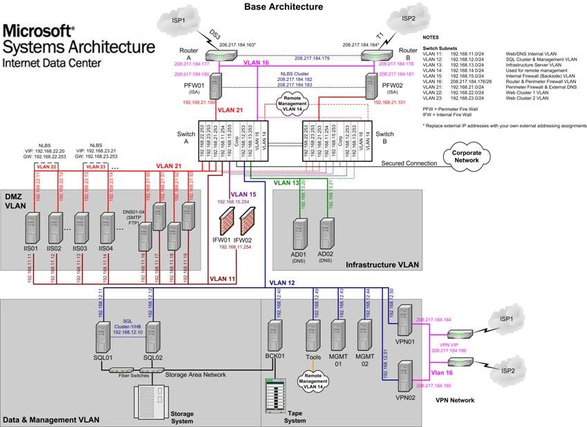
As previously
discussed, the Internet Data Center architecture
consists of a number of VLANs that help to manage the network traffic between
the various functions of the data center. It is important to be able to view the
complete design in a manner that is both detailed and understandable. To achieve
this, we have created the Base Architecture diagram that shows a detailed plan
of the Internet Data Center base
architecture. This diagram is included as an image in the appendix to this
chapter and also in Microsoft Visio source form, called Reference Architecture
Diagrams.vsd, in the appendix files that accompany this
guide.
The Internet Data Center design provides a model to be used
for implementing a comprehensive e-commerce solution. This chapter was intended
to provide details on the base design used for the network infrastructure
portion of the architecture.
Additional
areas of related design issues were discussed as appropriate.
Ultimately the
design you choose will be specific to your own company's requirements and
budget. However, the material covered in this chapter provides you with
information on the technologies available in each area of the network
infrastructure and provides you with a tried and tested architecture to start
working with.
This section provides
detail of the appendices provided for this chapter as part of the Internet Data Center architecture documentation.
The Base
Architecture diagram illustrates all the core technical components of the
architecture as described at reference level in this guide. In this case core
means the minimal data center services required to enable Internet facing
applications. It is intended as a useful reference whilst working your way
through, or selectively reading, the chapters in this guide. It should not be
seen as a definition of what the Internet
Data
Center
is due to the fact that customization is always required for specific customer
implementations. Even the services considered “core” may still need to be scaled
up or down, or implemented to a degree of availability that suits customer
requirements.